92-2486-01 Rev.
Overview This document describes the installation and use of the DMXrfNetII and DMXNetII Card options for the M-Class Mark II printers. After verifying the contents of the kit and the tools needed, follow the steps below to install and begin using the option. Keep this documentation for future reference. For your safety and to avoid equipment damage, always turn ‘Off’ power and unplug the printer’s power CAUTION cord before beginning this installation.
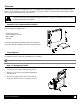
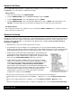
Preparing the Printer (continued) 4. Open the cover, loosen or remove the two Screws from the inside of the printer as shown. Screws 5. Lift the cover up and off the printer. Cover Assembly 6. Remove the two Screws and the Cover Plate from the rear of the printer.
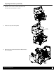
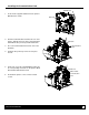
Installing the Communication Card Main Board 1. Insert the two supplied Standoffs into the printer’s Main Board as shown. Standoffs 2. Slide the Communication Card into the rear of the printer. Align the two holes in the Communication Card with the two previously installed Standoffs. Standoffs Communications Board 3. Press the Communication Card onto each of the Standoffs. 4. Install the two previously removed cover plate Screws. 5.
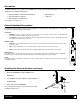
Introduction The M-Class MarkII series of printers are available with several Communication Card options. These cards can be equipped in the following configurations: Wired and Wireless Ethernet and USB Host* Wired Ethernet Wired and Wireless Ethernet USB Host* Wired Ethernet and USB Host* * Not avialable on the M-4206 model. External Hardware Descriptions The functions of the Interface Card’s external hardware are defined below.
Network Card Reset It is recommended that the printer’s communication settings be reset to factory defaults to avoid any conflicts in configuration. To reset the printer’s communication settings: Display Printers: 1. Turn on the printer and press the MENU BUTTON. 2. Using the DOWN BUTTON scroll to ‘COMMMUNICATIONS’ and press ENTER. 3. Using the DOWN BUTTON scroll to ‘NIC ADAPTER’ and press ENTER. 4. Using the DOWN BUTTON scroll to ‘SET FACTORY DEFAULTS’ and press ENTER. When prompted press the YES KEY.
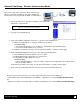
Network Card Setup - Wireless (Infrastructure Mode) After a successful setup is made via a wired connection, the Wireless connection (if equipped) can now be configured in infrastructure mode using an static or DHCP issued IP address. 1. Open your web browser. Type in the IP Address of the printer. The Default IP is: 192.168.10.26. Note: If you have assigned different IP Address to the printer, make sure to enter the correct IP Address. 2. The page to the right will appear: 3.
Network Card Setup - Wireless (Adhoc Mode) To configure the wireless card in Adhoc mode, you must configure your host computer to match the default settings of the printer. Your wireless network type must be Adhoc. Refer to your operating system’s or your wireless network card documentation for information on how to configure your computer. 1. Power on the printer. For display printers, enter the printer’s menu and navigate to the Communications/NIC Adapter/Quick Setup menu branch.
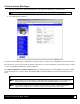
Printer’s Internal Web Pages 1. Open your web browser. Type in the IP Address of the printer. The Default IP is: 192.168.10.26. Note: If you have assigned different IP Address to the printer, make sure to enter the correct IP Address. 2. The following page will appear: The printer’s internal web pages are divided into 14 pages that are accessible via the navigation bar on the left-hand side. Most of the items on these pages mimic the printer's internal menu.
TCP/IP Configuration Page Static IP Settings IP Address Subnet Mask These are the static address the printer will use when “IP Discovery” is set to disabled or a valid IP could not be retrieved from a DHCP server. Default Gateway DHCP Settings Enable IP Discovery (DHCP, BOOTP, ect.) Controls IP Address discovery, where: Checked: Broadcasts over the network to receive addresses from the responsible server at startup.
Wifi Configuration Page WLAN Network Settings SSID Service Set Identifier that identifies the Module to connect to an AP. To make this connection, the Module and AP must have the same SSID. The SSID cannot contain spaces. Default setting is the MAC address of the wireless module. WLAN Network Type Specifies the type of network in which the Module will be used: Infrastructure = connects to WLAN using an AP. Ad Hoc = used to connect two peer-to-peer devices.
Wifi Configuration Page (continued…) Advanced Settings Maximum Transmission Rate Specifies the Module’s maximum wireless transmission rate. Default is 2 Mbps. Use Fixed Rate for Transmission Sets the 802.11 behavior for Ad Hoc mode. Default is 0. WLAN IP Settings DHCP Displays the current DHCP mode status. DHCP Fallback This is the IP address to use with DHCP is enabled and a DHCP server cannot be found.
DMX Config Utility DMXConfig (located on the Accessories CD-ROM) is a Windows based configuration utility that allows the user to make changes to the existing printer setup via a direct connection to the host computers serial and parallel connection. This is a vital tool for the use and configuration of wired and wireless printer setup (especially for printers without displays). Be sure to use the DMXConfig utility located on the Accessories CD-Rom that is included with your printer.
Enabling Adhoc Mode: Note: The following example uses the DMXConfig software utility to configure the printer. On printers equipped with a display, the same settings can be changed using the printer’s menu system via the front panel under COMMUNICATIONS > NIC ADAPTER. 1. Connect the host to the printer with a serial or parallel cable. 2. Turn on the printer. 3. Launch the DMXConfig utility. Query the printer by using the Query Printer toolbar button (top-left).
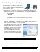
Installing the Printer Driver The following screen shots are taken from Windows 2000, other versions will be similar. 1 2 Start the Windows “Add Printer Wizard”. The following screen should appear, click ‘Next>’. Make sure that ‘Local Printer’ is selected and then click ‘Next’. 3 4 Select on ‘Create a new port:’ and then select ‘Standard TCP/IP Port’ from the drop down menu. Click ‘Next’ Click ‘Next’. 5 6 In the ‘Printer Name or IP Address:’ field enter the IP address of your printer.
9 10 Insert the Accessories CD-Rom and click ‘Browse’. Browse to the “\DRIVERS\Seagull” folder on the CDROM, make sure the file “for 95, 98, me, 2000, and xp.inf” is selected and click ‘OK’. 11 12 Click ‘OK’. Choose your printer from the list and then click ‘Next’. 13 14 Name your printer in the ‘Printer name:’ field. Next select whether or not to set this printer as your default printer. Then Click ‘Next’. Select whether or not to share this printer on your network.
USB Host Ports The USB Host Ports accept external memory storage devices for fonts, graphics, label formats, and firmware upgrades. Additionally, the USB Host Ports can accept a USB keyboard for direct data stand-alone input applications (e.g., Line Mode). USB Host: FCC/CE Certified 1.1 Module formatting and file downloading: Before initial use, an external memory device (USB thumbdrive) must be formatted (see Modules for details.). During formatting, a folder (‘H’) will be created in the module.
Wireless and Wired Ethernet Specifications The following list and table describes the key features and specifications of the wireless card. 802.11b wireless LAN (Wi-Fi) standards-based technology Highly integrated module includes radio, baseband and MAC processor, and application processor Wired 10/100Mbs RJ-45 Ethernet port.