
User guide


Overview 4
Introduction
The M-Class MarkII series of printers are available with two Communication Card options. These cards can be equipped
in the following configurations:
Wired Ethernet Wired and Wireless Ethernet
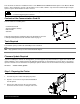
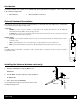
External Hardware Descriptions
The functions of the Interface Card’s external hardware are defined below. Depending on the configuration
of your card some items may not be present.
Connectors
ANTENNA is used to connect an antenna or coaxial cable for RF reception and transmission via this Multimedia
Communication Exchange (MMCX) Reverse Pin type connector.
10/100 BaseT is used to connect a 10/100 BaseT Ethernet cable via this RJ45 network connector. This port can not be used
for the setup of the wireless portion of the card.
Indicator Lights
ACTIVITY is a green indicator that flashes when the Card is not connected and scanning. The indicator will turn on when a
connection is made.
LINK is a yellow indicator that comes on when the Card is associated with an Access Point or Ad-hoc peer.
DATA is a green indicator that flashes when there is data transmitted between the printer and Host access point.
Label
This Label contains the MAC address of the Wireless Card. The MAC address of the printer’s wired port is listed on the printer’s
configuration test label.
ANT
ACTIVITY
LINK
DATA
WIRELESS
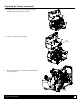
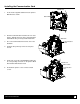
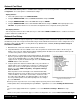
Installing the Antenna (wireless cards only)
1. Extend the Antenna then align the Base to the
Connector.
2. Turn the Base clockwise until fully seated and tight on
the Connector.
3. Raise and position the Antenna.
To avoid permenate damage, do not pull on the antenna when
handling the Wireless Card
Antenna
Connector
Base