92-2499-01 Rev.
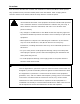
Overview This document describes the contents and installation of the M-Class Mark II RFID options. Only qualified service personnel should perform this installation. After verifying the kit contents and the tools needed, follow the steps below to install the option. • This RFID device complies with FCC Radio Frequency exposure limits for an uncontrolled environment. This equipment should be installed and operated CAUTION with a minimum distance of 20cm between the radiator and your body.
Contents The contents of the kit differ according to the type of RFID option: HF Option*: 1 Antenna 2 Regulator CCA 3 Mounting Plate 4 Power Cable 5 Comm Cable 6 Screw (3), M4 HD 8 7 Double-Sided Tape 8 Screw, M4 HD 25 9 Short Spacer (2), .34 X .31 10 Long Spacer, .25 X .
Tools Required A Phillips screwdriver is needed, and a PC with an Internet connection may also be required. Step 1: Checking Firmware A) Verify the firmware version in the printer: READY STOP Control Panel ERROR WED 09:32A 23APR2008 Press the TEST Button on the Control Panel. READY Using the DOWN Button, scroll to PRINT PAUSE CONFIGURATION and press TEST.
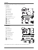
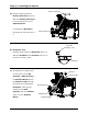
Cover Screws B) Remove the Cover Screws on the outside of the printer. Cover Cover Screws C) Raise the Cover. Loosen the Cover Screws on the Centerplate Centerplate then remove the Cover. D) Remove the Fascia, Printhead Assembly Thumbscrew and Tearbar (or other output attachment). Press the Printhead Thumbscrew Latch, and then raise the Printhead Assembly. Remove media from the printer.
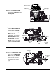
Step 3: Installing the Option Double-Sided Tape A) Peel the backing from the Double-Sided Tape (Item 7). Affix the Double-Sided Tape to the recessed area of the Antenna Mount. If installing the HF Option, proceed to B; otherwise, go to Antenna Mount C. RF Sheild (HF Option, only) B) HF Option, only – Peel the backing from the RF Shield (Item 12). Affix the RF Shield to the Antenna (Item 1) in the area as shown, right.
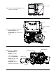
Antenna Cable Cableway Centerplate D) Route the Antenna Cable through the Cableway in the Centerplate. E) Loosen the Guide Screw Centerplate and the Heat Sink Screw then slide the Notched Tabs of the Mounting Plate (Item 3) underneath. Secure the Screw Guide Screw Notched Tab Mounting Plate to the Centerplate using the Screw (Item 6) and then tighten the Guide Screw Heat Sink Screw and the Heat Sink Screw.
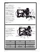
HF Option: G) Place the Washer (Item 11) and then the Long Spacer (Item 10) onto the Screw (Item 8). Place a Mounting Plate Short Spacer Short Spacer (Item 9) over the Long Spacer and HF Module Screw. Insert the Long Spacer and Screw Short Spacer through the HF Module (Item 14). Place a Short Spacer (Item 9) over the Long Spacer and Screw Screw then secure the assembled Long Spacer parts to the Mounting Washer Plate, as shown.
UHF Option: G) Secure the UHF Module (Item 10) to the Mounting Plate using the four Standoffs (Item 11) and four Screws (Item 8).
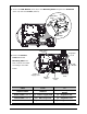
Step 3: Returning Operation A) Dress the installed cables into the existing cable bundle. RECHECK ALL Cover Screws CONNECTIONS. Lower and latch the Printhead Assembly. Replace the Cover. Reinstall and tighten the three Cover Screws. Cover Screws B) Replace the Tearbar and Thumbscrew (or other output attachment). Replace the Fascia. Tighten the Cover Centerplate Screws on the Centerplate. C) Plug the power cord into the AC Receptacle Power Switch and turn ON the Power Switch.
READY D) Enable the option by following the instructions Control Panel ERROR STOP USER MENU MEDIA SETTINGS PRINT CONTROL PRINTER OPTIONS below: SYSTEM SETTINGS EXIT MENU Step a Instruction Press the MENU Button on the Control Panel. SYSTEM ENTER TEST Displayed Message USER MENU MEDIA SETTINGS Using the DOWN Button, scroll to PRINTER PRINTER OPTIONS OPTIONS and press the ENTER Key. MODULES c Scroll to RFID and press ENTER. RFID d Press ENTER.