1 Safety Warnings and Cautions The following Warnings and Cautions are used throughout this manual: Warning: Warnings alert you to possible safety risks. Caution: Cautions alert you to the potential for equipment damage. General Safety Information Caution: This product is intended for indoor use only. All service procedures should be done by properly trained and qualified service personnel.
1 | Safety Internal Rewinder Installation Guide 2
2 Internal Rewind Installation Guide Tools Needed • 2.5mm Hex Head Wrench • 3mm Hex Head Wrench • 5mm Hex Head Wrench • 3mm Nut Driver • 7mm Nut Driver • #2 Phillips Screwdriver • Small Flat Blade Screwdriver Safety Overview Caution: ESD protection is required when performing these steps. Warning: The cover set may only be removed by a Datamax-O’Neil Authorized Service Center. Unauthorized service will void the manufacturer’s warranty.
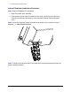
2 | Internal Rewind Installation Guide Internal Rewinder Installation Procedure Note: Retain all hardware for reassembly. 1. Open the media cover assembly. 2. If the present sensor option is installed on the cover, gently pry the sides of the cable chain outward to disconnect it from the present sensor cable connection cover. Note: If there is no present sensor mounted on the media cover, continue to step 5.
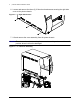
Internal Rewind Installation Guide | 2 3. Remove all four 7mm nuts securing the present sensor cable connection cover to the media cover. Figure: 2 - 2 PCB Cover 4. Disconnect the present sensor cable connector and route the connector (male) out of the opening. 5. Loosen all three (3) 2.5mm hex head screws from the upper cover mount. Note: For an easier re-installation, loosen but do not remove the screws.
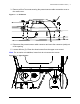
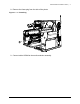
2 | Internal Rewind Installation Guide 6. Loosen and remove the three (3) 2.5mm hex head screws securing the right side cover to the printer chassis. Figure: 2 - 4 Right Side Screws 7. Lift and remove the cover assembly from the printer chassis. Caution: Exercise caution when removing the cover set assembly and secure it in a safe position where it will not be damaged.
Internal Rewind Installation Guide | 2 8. Remove the frame plug from the side of the printer. Figure: 2 - 6 Frame Plug 9. Connect cable 105048 to the media rewinder assembly.
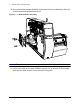
2 | Internal Rewind Installation Guide 10. Secure the media rewinder assembly to the printer frame by installing the three (3) socket head screws included with the kit. Figure: 2 - 7 Media Rewinder Assembly Caution: Ensure the cables are not damaged during the installation. 11. Connect the other end of cable 105048 to junction J12 of the main PCB assembly and route the cable so that it is free from all moving parts.
Internal Rewind Installation Guide | 2 12. Insert the media rewind hub through the printer frame and through the media rewinder assembly bearing.
2 | Internal Rewind Installation Guide 13. Install the supplied helical gear to the media rewind hub and secure it with the provided e-clip.
Internal Rewind Installation Guide | 2 14. Place the rewinder assembly cover over the rewinder and secure it with the included screws. Figure: 2 - 10 Rewinder Cover 15. Remove the roller cover panel.
2 | Internal Rewind Installation Guide 16. Insert a small, flat-blade screwdriver into the release opening, gently pry it to the left and remove the latch handle.
Internal Rewind Installation Guide | 2 17. Loosen and remove the screw securing the platen cover to the platen carriage and remove the platen cover.
2 | Internal Rewind Installation Guide 18. Insert the lower platen roller assembly through the opening in the printer chassis and route it through the print mechanism.
Internal Rewind Installation Guide | 2 19. Install the flanged bearing and secure it with the e-clip.
2 | Internal Rewind Installation Guide 20. If applicable, loosen and remove the thumbscrew securing the tear plate to the print mechanism and remove the tear plate. Figure: 2 - 17 Tear Plate 21. Install either the media rewind bracket or the peel plate. 22. Reinstall all other printer components in the reverse order as they were removed.