1 Safety Warnings and Cautions The following Warnings and Cautions are used throughout this manual: Warning: Warnings alert you to possible safety risks. Caution: Cautions alert you to the potential for equipment damage. General Safety Information Caution: This product is intended for indoor use only. All service procedures should be done by properly trained and qualified service personnel.
2 Media Hub Installation Instructions Safety Overview Caution: ESD protection is required when performing these steps. Warning: The cover set may only be removed by a Datamax-O’Neil Authorized Service Center. Unauthorized service will void the manufacturer’s warranty. Warning: The printer must be powered off and disconnected from utility power prior to performing these procedures. Failure to heed this warning may result in personal injury or damage to internal components.
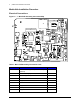
2 | Media Hub Installation Instructions Media Hub Installation Procedure Electrical Connections Figure: 2 - 1 Main PCB Assembly Connection Map J2 J3 J4 J10 J13 J20 J23 J22 J18 J19 J17 J15 J8 J16 J14 J12 J9 J7 J6 J5 J1 J25 J26 Table 1: Main PCB Assembly Connection Chart Junction Connection Cable J1 Wireless Module (Optional) or SD Memory (Optional) N/A J2 Front Panel Display 105047 J3 USB Host (Optional) 105055 J4 Present Sensor 105337 J5 Unpopulated N/A J6 Media Width
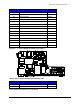
Media Hub Installation Instructions | 2 Junction Connection Cable J10 Ribbon Transport 105049 J11 Unpopulated N/A J12 Power Rewinder 105048 J13 Audio Alarm 105051 J14 Stepper Motor 104890 J15 Unpopulated N/A J16 Top-of-Form 105180 J17 Head Pressure Sensor 105052 J18 Unpopulated N/A J19 Paper Low Sensor 105193 J20 Cutter (Optional) 105190 J22 Printhead Data 105045 J23 Printhead Fan 105513 J25 GP I/O & Serial Ports 105785 J26 Power Supply Assembly (Bi-Directional
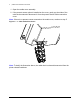
2 | Media Hub Installation Instructions 1. Open the media cover assembly. 2. If the present sensor option is installed on the cover, gently pry the sides of the cable chain outward to disconnect it from the present sensor cable connection cover. Note: If there is no present sensor mounted on the media cover, continue to step 5. Figure: 2 - 3 Cable Chain Disconnect Note: To clarify the illustration above, the cable chain is shown disconnected from the printer chassis backbone.
Media Hub Installation Instructions | 2 3. Remove all four 7mm nuts securing the present sensor cable connection cover to the media cover. Figure: 2 - 4 PCB Cover 4. Disconnect the present sensor cable connector and route the connector (male) out of the opening. 5. Loosen all three (3) 2.5mm hex head screws from the upper cover mount. Note: For an easier re-installation, loosen but do not remove the screws.
2 | Media Hub Installation Instructions 6. Loosen and remove the three (3) 2.5mm hex head screws securing the right side cover to the printer chassis. Figure: 2 - 6 Right Side Screws 7. Lift and remove the cover assembly from the printer chassis. Caution: Exercise caution when removing the cover set assembly and secure it in a safe position where it will not be damaged.
Media Hub Installation Instructions | 2 8. Loosen and remove both (2) socket head screws securing the rear chassis panel to the printer chassis and slide the panel out of the mounting slots.
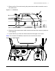
2 | Media Hub Installation Instructions 9. Loosen and remove the cover screw and cover from the rewinder assembly. Figure: 2 - 10 Remove Rewinder Cover 10. If the printer has the GP I/O option, disconnect the serial and GPIO connector from junction J25 on the main PCB assembly. 11. Loosen and remove both socket head screws securing the GP I/O & serial port subassembly to the printer chassis and then gently route the assembly and cable out of the chassis.
Media Hub Installation Instructions | 2 12. If the printer has the wireless option, loosen and remove the antenna mount thumbscrew from the wireless cable assembly. Figure: 2 - 12 Antenna 13. Disconnect the wireless cable assembly from the wireless module sub-assembly.
2 | Media Hub Installation Instructions 14. Loosen and remove the nut and washer securing the antenna cable assembly to the printer chassis. Figure: 2 - 14 Cable Assembly Cable Assembly Nut Washer 15. Carefully disconnect all of the connectors from the main PCB assembly and the power supply assembly.
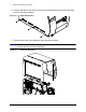
Media Hub Installation Instructions | 2 16. Loosen and remove both (2) screws securing the AC power inlet to the printer chassis. Figure: 2 - 15 AC Power Inlet 17. Loosen and remove the power supply ground screw.
2 | Media Hub Installation Instructions 18. Loosen and remove all three (3) power supply sub-assembly screws.
Media Hub Installation Instructions | 2 19. Loosen and remove both (2) socket head screws securing the power supply subassembly heat-sink to the printer chassis. Figure: 2 - 18 Power Supply Sub-Assembly Screws 20. Rotate the front (right side when viewing from the right side of the printer) of the power supply sub-assembly out of the chassis and then gently pull it completely out of the chassis. Caution: Exercise caution when maneuvering the sub-assembly out of the printer chassis.
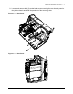
2 | Media Hub Installation Instructions 21. Loosen and remove the four (4) screws securing the main PCB assembly to the printer chassis. Figure: 2 - 19 Main PCB Assembly 22. Carefully remove the main PCB assembly by rotating the front (right side when viewing from the right side of the printer) of the assembly out of the printer chassis and then gently pulling the rest of the assembly out from the chassis.
Media Hub Installation Instructions | 2 23. Loosen and remove all three (3) socket head screws securing the media hanger to the printer chassis. Figure: 2 - 20 Media Hanger Mounting Screws Cable Channel Note: Be certain to support the media hanger during this step. 24. Remove the media hanger and carefully route the paper low sensor cable through the cable channel.
2 | Media Hub Installation Instructions 25. Remove the roller cover. Figure: 2 - 21 Roller Cover 26. Loosen and remove the four (4) screws securing the media plate to the base plate of the printer chassis. Figure: 2 - 22 Media Plate Note: These screws will not be reused with the media hub option.
Media Hub Installation Instructions | 2 27. Loosen and remove both (2) socket head screws securing the print carriage assembly to the base plate of the printer chassis. Figure: 2 - 23 Print Carriage Mounting Bolts 28. Loosen the center plate mounting bolts so the center plate can be raised enough to release the media plate from the printer chassis.
2 | Media Hub Installation Instructions 29. Gently raise the center plate and remove the media plate from the printer. 30. Route the paper low sensor cable through the cable channel in the printer chassis. Caution: Be certain to route it so the cable will not be damaged during reassembly or operation. Figure: 2 - 25 Paper Low Sensor Cable Channel 31. Gently raise the center plate and insert the media hub assembly.
Media Hub Installation Instructions | 2 32. Install the four (4) socket head screws (included in the kit) to secure the media hub assembly to the printer chassis. Figure: 2 - 26 Media Hub Assembly Mounting Screws 33. Reinstall the printer components in the reverse order as they were disassembled.