1 Safety Warnings and Cautions The following Warnings and Cautions are used throughout this manual: Warning: Warnings alert you to possible safety risks. Caution: Cautions alert you to the potential for equipment damage. General Safety Information Caution: This product is intended for indoor use only. All service procedures should be done by properly trained and qualified service personnel.
2 Present Sensor Installation Tools Needed • 2.5mm Hex Head Wrench • 3mm Hex Head Wrench • 7mm Nut Driver • #1 Phillips Screwdriver • #2 Phillips Screwdriver Safety Overview Caution: Electrostatic discharge (ESD) protection is required when performing these steps. Warning: The cover set may only be removed by a Datamax-O’Neil Authorized Service Center. Unauthorized service will void the manufacturer’s warranty.
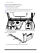
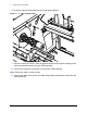
2 | Present Sensor Installation Present Sensor Installation Procedure Note: Retain all hardware for reassembly. 1. Open the media cover assembly. 2. Loosen all three (3) 2.5mm hex head screws from the upper cover mount. Note: For an easier re-installation, loosen but do not remove the screws. Figure: 2 - 1 Upper Screws 3. Loosen and remove the three (3) 2.5mm hex head screws securing the right side cover to the printer chassis. Figure: 2 - 2 Right Side Screws 4.
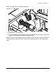
Present Sensor Installation | 2 Caution: Exercise caution when removing the cover set assembly and secure it in a safe position where it will not be damaged. Figure: 2 - 3 Lift Cover Assembly 5. Remove the center plate plug.
2 | Present Sensor Installation 6. Press the cable chain bracket into the center plate opening. Figure: 2 - 5 Cable Chain Bracket 7. Route the cable (SP105337) from the present sensor kit through the opening of the cable chain bracket and to the main PCB assembly. 8. Connect the connector to junction J4 of the main PCB assembly. Note: Ensure the cable is safely routed. 9. Connect the cable chain end to the cable chain bracket and press the wires into the cable chain slot.
Present Sensor Installation | 2 Note: The cable chain slot should face down. Figure: 2 - 6 Cable Chain Cable slot 10. Reinstall the cover assembly. 11. If not assembled, seat the present sensor sub-assembly into the support mount and fasten it to the front panel using the supplied screw. Note: There are three positions where the present sensor may be mounted. Select the one that places the present sensor closest to the identifying mark on the media being used.
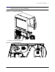
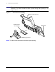
2 | Present Sensor Installation Caution: Ensure the ribbon cable is securely connected to the present sensor subassembly. The cable should be routed upward through the opening in the support mount. Figure: 2 - 7 Present Sensor Assembly Ribbon Cable Opening Present Sensor Sub-Assembly Front Panel Support Mount Note: The ribbon cable should be routed through the opening.
Present Sensor Installation | 2 12. Fasten the present sensor assembly to the printer front cover. Figure: 2 - 8 Present Sensor Panel Installation Media Cover Open Front Cover 13. If not assembled, fasten the present sensor PCB assembly to the mounting plate using the supplied screws.
2 | Present Sensor Installation 14. Connect the ribbon cable from the present sensor to the connector on the PCB assembly and connect the remaining extension cable connector to the other cable connection. Note: Ensure the ribbon cable is seated evenly in the connector before securing the pressure fitting tab. 15. install the PCB assembly, mounting plate and cover and secure it with the two (2) screws provided in the kit. Note: Route the cable out of the bottom corner of the cover.
Present Sensor Installation | 2 16. Ensure the cable is routed properly through the ferrite. Figure: 2 - 11 Cable Route To the Main PCB Assembly From Present Sensor PCB Assembly Note: The cable should be routed through the ferrite as shown.
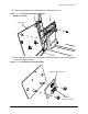
2 | Present Sensor Installation 17. Insert the connector through the slot in the cover. Note: The ferrite should be adhered to the inside of the cover with tape. Figure: 2 - 12 Present Sensor Ferrite and Cover Connector Slot Ferrite Note: The cable should be routed through the ferrite as shown. 18. Secure the cover to the media cover with three nuts. Note: Ensure the cable going to the present sensor PCB assembly is routed through the opening on the left rear of the cover.
Present Sensor Installation | 2 Note: The remaining nut will be installed on a future step. Figure: 2 - 13 Cover Installation 19. Securely connect the connectors from the present sensor PCB assembly and the main PCB assembly.
2 | Present Sensor Installation 20. Insert the connectors through the opening in the box cover and secure the cable chain to the box cover. Figure: 2 - 15 Cable Chain Connection Note: Ensure the cable chain snaps into place over the extrusions.
Present Sensor Installation | 2 21. Route the left side of the cable cover into the opening in the PCB assembly cover, route the cable under the cover and secure the cable cover over the box cover with the remaining nut. Figure: 2 - 16 Cable Cover Installation Insert this end first Cable Cover Cable Note: Ensure the cable is positioned correctly under the cable cover to prevent damage. 22. Install the warning label on the upper printhead mechanism. Figure: 2 - 17 Warning Label aution Label 23.