1 Safety Warnings and Cautions The following Warnings and Cautions are used throughout this manual: Warning: Warnings alert you to possible safety risks. Caution: Cautions alert you to the potential for equipment damage. General Safety Information Caution: This product is intended for indoor use only. All service procedures should be done by properly trained and qualified service personnel.
2 Thermal Transfer Installation Guide Tools Needed • 2.5mm Hex Head Wrench • 5mm Hex Head Wrench • 7mm Nut Driver • #1 Phillips Screwdriver • #2 Phillips Screwdriver Safety Overview Caution: ESD protection is required when performing these steps. Warning: The cover set may only be removed by a Datamax-O’neil Authorized Service Center. Unauthorized service will void the manufacturer’s warranty.
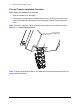
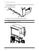
2 | Thermal Transfer Installation Guide Thermal Transfer Installation Procedure Note: Retain all hardware for reassembly. 1. Open the media cover assembly. 2. If the present sensor option is installed on the cover, gently pry the sides of the cable chain outward to disconnect it from the present sensor cable connection cover. Note: If there is no present sensor mounted on the media cover, continue to step 5.
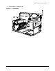
Thermal Transfer Installation Guide | 2 3. Remove all four 7mm nuts securing the present sensor cable connection cover to the media cover. Figure: 2 - 2 PCB Cover 4. Disconnect the present sensor cable connector and route the connector (male) out of the opening. 5. Loosen all three (3) 2.5mm hex head screws from the upper cover mount. Note: For an easier re-installation, loosen but do not remove the screws.
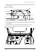
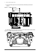
2 | Thermal Transfer Installation Guide 6. Loosen and remove the three (3) 2.5mm hex head screws securing the right side cover to the printer chassis. Figure: 2 - 4 Right Side Screws 7. Lift and remove the cover assembly from the printer chassis. Caution: Exercise caution when removing the cover set assembly and secure it in a safe position where it will not be damaged.
Thermal Transfer Installation Guide | 2 8. Remove both (2) frame plugs.
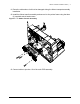
2 | Thermal Transfer Installation Guide 9. Secure the ribbon spool cover to the printer frame with both (2) screws and washers. Figure: 2 - 7 Ribbon Spool Cover Screws Washers 10. If applicable, connect the cable to junction J1 of the ribbon transfer controller board.
Thermal Transfer Installation Guide | 2 11. Route the cable where it will not be damaged during the ribbon transport assembly installation. 12. Install the ribbon transfer assembly and secure it to the printer frame using the three (3) supplied socket head screws. Figure: 2 - 9 Ribbon Transfer Assembly 13. Connect cable to junction J10 of the main PCB assembly.
2 | Thermal Transfer Installation Guide 14. Insert the ribbon hub and the ribbon rewind hub through the ribbon spool cover and through the bearings of the ribbon transport assembly.
Thermal Transfer Installation Guide | 2 15. Install both (2) gears, both (2) wave washers and both (2) e-clips to the ribbon hub and ribbon rewind hub shafts.
2 | Thermal Transfer Installation Guide 16. Using the supplied screw, install the power ribbon transport cover to the ribbon transport assembly. Figure: 2 - 12 Power Ribbon Transport Assembly Cover 17. Reinstall all other printer components in the reverse order as they were disassembled.