1 Safety Warnings and Cautions The following Warnings and Cautions are used throughout this manual: Warning: Warnings alert you to possible safety risks. Caution: Cautions alert you to the potential for equipment damage. General Safety Information Caution: This product is intended for indoor use only. All service procedures should be done by properly trained and qualified service personnel.
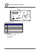
1 Wireless Installation Instructions Figure: 1 - 1 Wireless Option 1 6 4 5 3 2 Table 1: Wireless Assembly Part Description 1 Standard 802.11b/g Wireless Assembly 2 Swivel Base Antenna 3 6” Wireless Cable Assembly 4 3.18mm X 6.35mm Micro-cellular Foam 5 Standard 802.11b/g Wireless Module SubAssembly 6 Label, FCC ID Tools Needed • 2.
1 | Wireless Installation Instructions Safety Overview Caution: ESD protection is required when performing these steps. Warning: The cover set may only be removed by a Datamax-O’Neil Authorized Service Center. Unauthorized service will void the manufacturer’s warranty. Warning: The printer must be powered off and disconnected from utility power prior to performing these procedures. Failure to heed this warning may result in personal injury or damage to internal components.
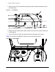
Wireless Installation Instructions | 1 Wireless Installation Procedure Note: Retain all hardware for reassembly. 1. Open the media cover assembly. 2. If the present sensor option is installed on the cover, gently pry the sides of the cable chain outward to disconnect it from the present sensor cable connection cover. Note: If there is no present sensor mounted on the media cover, continue to step 5.
1 | Wireless Installation Instructions 3. Remove all four 7mm nuts securing the present sensor cable connection cover to the media cover. Figure: 1 - 3 PCB Cover 4. Disconnect the present sensor cable connector and route the connector (male) out of the opening. 5. Loosen all three (3) 2.5mm hex head screws from the upper cover mount. Note: For an easier re-installation, loosen but do not remove the screws.
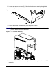
Wireless Installation Instructions | 1 6. Loosen and remove the three (3) 2.5mm hex head screws securing the right side cover to the printer chassis. Figure: 1 - 5 Right Side Screws 7. Lift and remove the cover assembly from the printer chassis. Caution: Exercise caution when removing the cover set assembly and secure it in a safe position where it will not be damaged. Figure: 1 - 6 Lift Cover Assembly 8. Insert the wireless module sub-assembly into its connection point on the main PCB assembly.
1 | Wireless Installation Instructions Note: Once it is fully inserted, it should click into place.
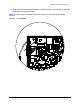
Wireless Installation Instructions | 1 9. Insert the foam strip directly behind the wireless module sub-assembly on the main PCB board in the outlined area. Note: The foam strip is intended to keep the module from accidentally becoming ejected.
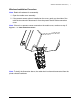
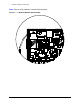
1 | Wireless Installation Instructions 10. Carefully remove the frame plug from the back of the printer. Figure: 1 - 9 Frame Plug Caution: Exercise caution when removing the plug to ensure the printer is not damaged.
Wireless Installation Instructions | 1 11. Insert the cable assembly through the frame and secure it with the included washer and nut. Figure: 1 - 10 Cable Assembly Cable Assembly Nut Washer 12. Connect the cable assembly to the wireless module sub-assembly and ensure the connection is secure.
1 | Wireless Installation Instructions Caution: Any pressure exerted on the wireless module sub-assembly could damage the component. Exercise caution when making this connection.
Wireless Installation Instructions | 1 13. Install the antenna on the cable assembly and secure it by tightening the antenna thumbscrew.
1 | Wireless Installation Instructions 14. Apply the FCC ID label just above the antenna base. Figure: 1 - 13 FCC ID Label 15. Reinstall all other printer components in the reverse order as they were disassembled. Note: Refer to the User’s Guide when setting up wireless communications.