92-2416-01 Rev.
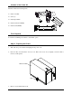
Contents of the Cutter Kit This kit contains the following items: Cutter Assembly 1 Screw (2) Cutter Input Guide 2 3 Cutter Cable (Non-ROHS) Cutter Cable (ROHS) 4 5 Tools Required You will need a Phillips screwdriver to install this option. Step A: Preparing the Printer 1. Turn ‘Off’ the power switch and unplug the AC power cord. 2. Insert the Key and unlock the Access Cover. Raise the Access Cover slightly, and then shift it forward, off the printer. Access Cover Key 3.
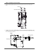
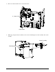
. If present, remove the Memory Module from the Module Bay. Remove the two Inside Cover Screws and loosen the two Outside Cover Screws. Raise the Electronics Cover off the printer. Inside Cover Screws Electronics Cover Module Bay Outside Cover Screws 5. Remove the Mounting Screws securing the Cover Plate, then remove the plate.
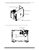
Cover Plate Mounting Screws 6. Unlock and raise the printhead. Remove the two Screws securing the Tear Input Guide, and then remove the guide.
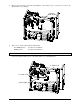
Step B: Installing the Cutter Assembly 1. Install the Cutter Input Guide (Item 3) and secure it using the two Screws removed in Step A-6, above. Screws Cutter Input Guide 2. Carefully slide the Cutter Assembly (Item 1) into the printer. Ensure that the Guide Pins on the assembly fit into the Locator Holes in the printer, and then secure the Cutter Assembly in place using the two Mounting Screws (Item 2).
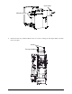
3. Remove the Screw that secures the Strain Relief to the chassis. (It is not necessary to remove the Strain Relief or any cabling). Screw & Strain Relief 4. There are two cutter cables included with this kit: Non-ROHS printers: ROHS printers: Use Item 4 (32-2430-01) Use Item 5 (32-2628-01) The serial label on the rear of the printer will state if the printer is ROHS compliant. Connect the Cutter Cable from J1 of the Cutter CCA to J1 of the Main CCA..
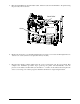
5. Place the Strain Relief around the Cutter Cable, and then secure the Strain Relief to the printer using the previously removed Screw. Strain Relief Main CCA Screw 6. Replace the electronics cover. Install and tighten the two inside cover screws and then tighten the two outside cover screws. (If removed, replace the memory module.) 7. Reconnect the interface cable(s). Plug in the AC power cord and turn ‘On’ the power switch. This completes the installation procedure.
Cutter Maintenance Cutter maintenance is recommended after every 5,000 − 10,000 cuts, an interval that varies depending upon the type of ticket stock being used. The need for cleaning may also be indicated when the cut operation becomes slow or labored.
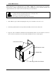
4. Remove the Cutter Cable from J1 on the Cutter CCA. J1, Cutter CCA Cutter Cable 5. While supporting the Cutter Assembly, remove the two Mounting Screws then carefully slide out the assembly.
6. Using a soft brush or compressed air, remove all debris from inside the printer. 7. Using a soft brush or compressed air, remove all debris from the Cutter Assembly. Then, using a cotton swab dampened with isopropyl alcohol, clean the Cutter Blade surfaces until all build-up is removed. 8. Carefully slide the Cutter Assembly into the printer. Ensure that the Guide Pins on the assembly fit into the Locator Holes in the printer, and then secure the cutter in place using the two Mounting Screws.
Cutting Requirements Table 1, below, lists the media requirements for use in the cutter mechanism. For a complete listing of these requirements, see the Operator’s Manual. Description Inches Ticket Width Minimum Millimeters 2.0 51 Inches Maximum Millimeters 3.