92-2415-01 Rev.
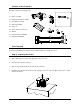
Contents of this Cutter Kit This kit contains the following items: 1 2 Cutter Assembly 3 Cutter Circuit Card Assembly Front Plate Assembly Cutter Input Guide Screw (3) 4 5 Screw, with star washer (2) 6 7 Washer Cutter Cable (Non-ROHS) 8 Cutter Cable (ROHS) 9 Tools Required You will need a Phillips screwdriver and an 8 mm Nut Driver to install this option. Step A: Preparing the Printer 1. Turn ‘OFF’ the power switch and unplug the AC power cord. 2.
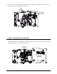
5. Remove the two Screws that secure the Electronics Cover to the printer. 6. Grasp the Electronics Cover from bottom and, while pulling down slightly to free the Catches, remove the cover. Front Panel Electronics Cover Catches Screws 7. Unlock and raise the printhead. Remove the two Screws that secure the Tear Input Guide and then remove the guide.
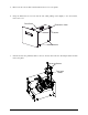
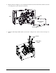
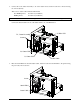
8. Remove the two Screws that secure the Cover Plate and then remove the plate. Screws Cover Plate 9. Remove the two Screws that secure the Power Supply Cover. Then remove the cover by sliding it slightly backward and off the printer.
10. Remove the four Nuts that secure the Front Plate Assembly to the printer and then remove the assembly. Proceed to Step B of this procedure. Nuts (four total) Front Plate Assembly Step B: Installing the Cutter Assembly 1. Insert the Standoffs on the Front Plate Assembly (Item 3) into the printer, and secure the assembly using the four Nuts removed in Step A-10, above.
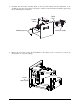
2. Replace the Power Supply Cover by inserting the Tabs into the Slots in the frame, and then secure the cover using the two previously removed Screws. Tabs Slots Power Supply Cover Screws 3. Install the Cutter Input Guide (Item 4) and secure it using the two Screws removed in Step A-7, above.
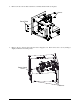
4. Carefully slide the Cutter Assembly (Item 1) into the printer. Ensure that the Guide Pins on the assembly fit into the Locator Holes in the printer, and then secure the Cutter Assembly in place using the two Mounting Screws (Item 5). Guide Pins Locator Holes Mounting Screws Cutter Assembly 5. Remove the Screw that secures the Strain Relief to the chassis. (It is not necessary to remove the Strain Relief or reroute any cabling).
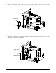
6. Install the Cutter CCA (Item 2) into the printer by placing the Tab into the Locator Hole in the Baseplate. Cutter CCA Locator Hole Baseplate Tab 7. Insert the Screw (Item 6) into the Washer (Item 7), and then securely fasten the Cutter CCA to the Baseplate using the Screw and Washer.
8. Connect P1 of the Cutter Assembly to J2 of the Cutter CCA, and then secure the connection using two Screws (Item 6). There are two cutter cables included with this kit: Non-ROHS printers: ROHS printers: Use Item 8 (32-2430-01) Use Item 9 (32-2628-01) The serial label on the rear of the printer will state if the printer is ROHS compliant. Connect the Cutter Cable from J1 of the Cutter CCA to J1 of the Main CCA. J1, Main CCA P1, Cutter Assembly Screws J2, Cutter CCA J1, Cutter CCA Cutter Cable 9.
10. Replace the electronics cover and secure it using the two previously removed screws. Proceed to Step C, below. Step C: Adjusting the Front Plate Brushes For proper ticket stacking following the cut operation, the Brushes within the Front Plate Assembly must be adjusted, as follows: 11. Ensure that the Brushes in the Front Plate Assembly are at the widest setting (if necessary, slightly loosen the Screws and reposition the Brushes; see the drawing below). 12.
Cutter Maintenance Cutter maintenance is recommended after every 5,000 − 10,000 cuts, an interval that varies depending upon the type of ticket stock being used. The need for cleaning may also be indicated when the cut operation becomes slow or labored.
5. Unlock and raise the printhead. While supporting the Cutter Assembly, remove the two Mounting Screws, and then carefully slide the Cutter Assembly out of the printer. Cutter Assembly Mounting Screws 6. Using a soft brush or compressed air, remove all debris from the printer and Ticket Door area. 7. Using a soft brush or compressed air, remove all debris from the Cutter Assembly. Then, using a cotton swab dampened with isopropyl alcohol, clean the Cutter Blade surfaces until all build-up is removed.
9. Reconnect P1 to the Cutter CCA and secure it with the two previously removed screws. Screws Cutter CCA P1 10. Replace the electronics cover and secure with the two previously removed screws. 11. Lower and lock the printhead assembly then gently lower the printer into its enclosure. 12. Reconnect the interface cable(s). Plug in the AC power cord and turn ‘On’ the power switch. This completes the cleaning procedure. Reload ticket stock.
Cutting Requirements Table 1, below, lists the media requirements for use in the cutter mechanism. For a complete listing of these requirements, see the Operator’s Manual. Minimum Inches Millimeters Description Ticket Width 2.0 51 Maximum Inches Millimeters 3.