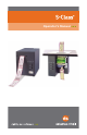
Operator’s Manual
Copyright Information CG Triumvirate is a trademark of Agfa Corporation. Copyright Information In no event shall Datamax-O’Neil be liable to the purchaser for any indirect, special or consequential damages or lost profits arising out of or relating to Datamax-O’Neil’s products, or the performance or a breach thereof, even if Datamax-O’Neil has been advised of the possibility thereof.
Agency Compliance and Approvals C US UL60950-1: 2nd Edition CSA C22.2 No. 60950-1-07 2nd Edition Listed Gost-R The manufacturer declares under sole responsibility that this product conforms to the following standards or other normative documents: EMC: EN 55022 (2006, A1:2007) Class B EN 55024 (1998, A1:2001, A2:2003) Safety: This product complies with the requirements of IEC 60950-1 2nd Edition, 2005-12 ROHS: 2002/95/EC LVD: 2006/95/EC FCC: This device complies with FCC CFR 47 Part 15 Class A.
Important Safety Instructions: This printer has been carefully designed to give many years of safe and reliable performance; however, as with all types of electronic equipment, there are some basic precautions that should taken to avoid personal injury or damage to the printer: Carefully read the installation and operating instructions provided with this printer. Read and follow all warning instruction labels on the printer. Place ST Models on a flat, firm surface; mount SV Models in rigid enclosure.
Contents Overview ..................................................................................................1 1.0 About the Printer ............................................................................. 1 1.0.1 Standard Features .......................................................... 2 1.0.2 Optional Features............................................................ 3 Getting Started ........................................................................................5 2.
4.1 Stock ID Selections ....................................................................... 33 4.2 Start of Print & Cut/Tear Adjustment............................................. 35 4.3 Operational Database Modification ............................................... 36 4.3.1 4.4 Database Modification Example ................................... 39 Maintenance .................................................................................. 40 4.4.1 Printhead Cleaning.........................
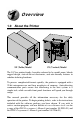
Overview 1.0 About the Printer ST (Table) Model SV (Vertical) Model The S-Class printer family, hereafter referred to by model name, blends rugged design, state-of-the-art electronics, and user-friendly features to redefine ticketing hardware. To process complicated formats quickly, the printer is equipped with a 32-bit microprocessor and four megabytes of memory.
1.0.
1.0.2 Optional Features Many optional features are available for this printer: Cutter and Tray (ST Models only) This device automatically cuts ticket stock. Stock thickness can range from .0025 inch (.06 mm) up to .008 inch (.2 mm). A tray, capable of stacking a minimum of 100, 3.5-inch (88.9 mm) wide tickets, collects the cut tickets. Order this feature when placing your printer order.
4 S-Class
Getting Started 2.0 Unpacking Inspect the shipping container(s) for damage; if evident, notify the shipping carrier to report the nature and extent of the damage before proceeding. The printer is carefully packaged to avoid any damage during transit. In order to operate the printer, you will need to remove the packaging materials placed there for shipment. Complete the following steps prior to connecting power or attempting to load ticket stock.
2.0.1 Inspection After inspecting the printer, check the remaining contents of the box. In addition to this manual, the following items should be included: Ticket Printer Power cord Keys (ST Models only) Accessories CD-ROM Special or additionally purchased items. Important Notice: 2.0.2 Additional Requirements In addition to the above-mentioned items, the following items are necessary for ticket printing.
Setting-Up the Printer This section details the connections, loading methods, and resident ticket formats of the printer. 3.0 Power Connection Note: Before connecting the AC Power Cord or interface cables to the printer, ensure the Power On/Off Switch is in the ‘Off’ position. Place the printer on a firm, level surface. Ensure that the Power Switch on the Printer is in the ‘Off’ position.
3.1 Interfacing The printer can be connected to the host via the parallel, USB, or serial, The printer will automatically connect to the first port that delivers valid data. Once established, the printer’s power must be cycled ‘Off’ and ‘On’ to change an interface connection.
3.1.1 Automatic Parser Mode Detection From the factory, the printer will automatically interpret the data received from the host to set the Parser Mode. Note: When set to ‘Auto,’ the printer assumes its parser mode according to the first character received. If the first character is a < (ASCII control character 3C, as transmitted by most ticketing software packages), the printer will assume the desired DTPL parser mode.
3.2 Loading Ticket Stock The procedure to load the printer differs depending upon the model, options, and stock type being used. These differences are detailed below. 3.2.1 ST Models Note: If your printer is equipped with the Roll Hanger option but you want to use an internal fan-fold ticket source instead, the Roll Hanger must be removed. Remove the Roll Hanger by turning it counter-clockwise to unscrew it from the centerplate of the printer.
“Standard Media Sensor” using Fan-Fold Stock – With the ticket TOF Marks facing ‘down’ (away from you), place the ticket stock in the bottom of the printer. (If using an external supply, route the ticket stock into the printer through the Rear or Bottom Slots.) Ensure that the Printhead Latch is in the ‘Locked’ position.
“Print Side Media Sensor” using Fan-Fold Stock – With the ticket TOF Marks facing ‘up’ (toward you), place the stock in the bottom of the printer. (If using an external supply, route the ticket stock into the printer through the Rear or Bottom Slots.) Ensure that the Printhead Latch is in the ‘Locked’ position.
“Standard Media Sensor” using Roll Stock – Mount the roll of ticket stock on the Roll Hanger so that it unwinds in the direction shown by the arrow in the drawing below. (The TOF Marks must be wound inward on the roll; see Section 6 for ticket stock specifications). Ensure that the Printhead Latch is in the ‘Locked’ position.
“Print Side Media Sensor” using Roll Stock – Mount the roll of ticket stock on the Roll Hanger so that it unwinds in the direction shown by the arrow in the drawing below. (The TOF Marks must be wound outward on the roll; see Section 6 for ticket stock specifications). Ensure that the Printhead Latch is in the ‘Locked’ position. Unlocked Locked Roll Hanger Loosen the Thumbscrew and adjust the Media Guides to fit the width of the ticket stock.
Thumbscrew Media Guides (Too Loose) Thumbscrew Media Guides (Too Tight) Slide the ticket stock farther into the Media Guides until it is grabbed by the loading mechanism, and then allow the printer to complete the positioning process. Close the Access Cover. Note: If automatic loading doesn’t occur, try the following: 1) Ensure that the Printhead Latch is locked.
3.2.2 SV Models Plug in and turn ‘On’ the printer. Bring the stock up to the Media Guides (the TOF Marks on the tickets should be facing away from the Printhead Latch; see Section 4). Ensure that the Printhead Latch is locked. Locked Unlocked Printhead Latch Front Panel Thumbscrew Media Guides Ticket Stock Loosen the Thumbscrew and adjust the Media Guides to fit the width of the ticket stock as described in Step 5 of Section 3.2.1. Slide the ticket stock through the Media Guides.
Note: If automatic loading doesn’t occur, try the following: 1) Ensure that the Printhead Latch is locked. 2) Press the PAUSE button (the On-Line Indicator will go ‘Off’) and then repeatedly press the F2 button while gently pushing the stock forward until the printer grabs the ticket. 3) Press the PAUSE button (to return to the on-line mode). If the ticket was not fed to a proper position, the Media Sensor may need adjustment; see Section 4 for details.
3.3 Using the Front Panel The Front Panel is comprised of a ticket exit, darkness control, three indicator lights, and three dual-purpose buttons.
Ticket Exit The printed tickets are expelled from this opening. Darkness Control The Darkness Control adjusts the contrast of the printing on the tickets: turning the control clockwise darkens the print, while turning the control counterclockwise lightens it. Darkness can also be controlled through software. Indicators For a brief period after power-up (about 20 seconds), all three indicators will remain on while the printer performs internal diagnostics.
Dual-Purpose Buttons Depending upon the printer’s mode, the buttons function as follows: On-Line Mode Button Functions (On-Line, as denoted by the On-Line Indicator being ‘On’) PAUSE: Press this to temporarily stop printing (pause mode) or to enter the off-line mode. Press this button in pause mode to resume printing from the point stopped; or, if in off-line mode press to return to the on-line mode. FEED: Press this button to advance the ticket stock to the next print position.
Power-Up and Off-Line Mode Button Functions (Off-Line, as denoted by the On-Line Indicator being ‘Off’) F2: Three functions: (a) Press momentarily to advance ticket stock, or to manually load ticket stock. (b) Press and hold during power-up to print a Configuration and Test Pattern Ticket, and enter Character Dump mode. (c) Press and hold to enter the Operational Database Modification mode; see Section 4.3 for details.
3.4 Resident Formats Several formats are stored in memory for useful setup, operational, and diagnosis information. Load stock that is at least 2 inches (51 mm) wide to capture all the data and patterns on these resident formats. 3.4.1 Configuration Ticket The Configuration Ticket provides firmware, memory, and options information (depending upon the model, equipment, and firmware this information will vary). To print a Configuration Ticket: With stock loaded, turn the printer ‘On’.
3.4.2 Test Pattern Ticket The Test Pattern Ticket is a resident format that can be used to determine general print quality and the condition of the printhead; see the examples below. With stock loaded, turn the printer ‘On’. Press the PAUSE button to put the printer in the off-line mode. Simultaneously press the F1 and F2 Buttons. A “Good” Test Pattern Ticket: Consistent patterns across the width of the ticket indicate that the printhead is operating normally.
3.4.3 Internal Test Ticket The Internal Test Ticket is another resident format that is another useful indicator of print quality. This ticket features various font sizes and barcodes (the sample below was printed using the ST-3210). To print an Internal Test Ticket: With stock loaded, turn the printer ‘On’. Press the PAUSE button to enter the off-line mode. Press the F3 button.
3.5 Resetting the Printer There are two different reset levels possible for the printer: 3.6.1 Warm Reset To reset the printer and return to the on-line mode: Press the PAUSE button to go off-line and then press the F1 + F3 Buttons simultaneously. 3.6.2 Factory Default Reset To return the printer to default database settings (see the table below), perform the following procedure. Turn the printer ‘Off’. Press and hold the PAUSE/F1, FEED/F2 and TEST/F3 Buttons while turning ‘On’ the printer.
3.6 Keypad Lockout The Keypad Lockout Function stops the operator's ability to enter the offline functions in the printer’s menu. To enable the lockout feature: Press and hold the PAUSE/F1 and FEED/F2 buttons while turning ‘On’ the printer. To disable the lockout feature: Press and hold the FEED/F2 and TEST/F3 buttons while turning ‘On’ the printer.
Adjustments and Maintenance This section details important adjustments, settings and periodic maintenance requirements that will ensure optimum performance. 4.0 Media Sensor Adjustment The Media Sensor in the printer has two functions: (1) To sense the presence of ticket stock; and, (2) To detect the Top of Form (TOF) Mark (a black stripe, rectangle, or square, as shown in the illustration below). The Media Sensor must be adjusted so that it can “see” the TOF Marks on the ticket.
4.0.1 ST Model Media Sensor Adjustment The ST Model can be equipped with either a Standard or a Print Side Media Sensor. Follow the appropriate procedure for the Media Sensor in your printer: Adjusting the Standard Media Sensor – Turn ‘Off’ the Power Switch. Open the Access Cover.
Printhead Assembly Media Sensor Slide Printhead Latch Ticket Stock Lower the Printhead Assembly and lock the Printhead Latch. Turn ‘On’ the printer and load ticket stock; see Section 3.2. Lower and lock the Access Cover. To verify the alignment, press the FEED button several times – the stopping point should be the same for each ticket that is output. Note that if the Fault Indicator illuminates, the sensor needs to be repositioned (see Section 5 for a complete listing of possible causes).
Adjusting the Print Side Media Sensor – Turn ‘Off’ the Power Switch. Open the Access Cover. Loosen the Thumbscrew and adjust the Media Guides to fit the width of the ticket stock: The guides should be positioned so that there is no side-to-side ticket movement (too loose), but not so close as to cause friction or bowing of the ticket (too tight). (See Step 5 in Section 3.2.1 for an illustration). Once properly positioned, tighten the Thumbscrew to secure the Media Guides in place.
Grasp the Nut to move the Media Sensor. Position the sensor so that it can see the Quiet Zone and the TOF Marks on the ticket stock, as described in Section 4.0. Tighten the Nut securely. Turn ‘On’ the printer and load ticket stock; see Section 3.2. To verify the alignment, press the FEED button several times – the stopping point should be the same for each ticket that is output.
Media Sensor Printhead Assembly Printhead Latch Ticket Stock Raise the Printhead Assembly and lock the Printhead Latch. Turn ‘On’ the printer and load ticket stock; see Section 3.2. To verify the alignment, press the FEED button several times – the stopping point (TOF) should be the same for each ticket output.
4.1 Stock ID Selections The printer maintains a selection of 10 user modifiable stock setups. Each setup defaults to a specific print width, start print position and cut/tear position, where: The Print Width is the print distance across the ticket. The Start of Print Position is the distance, measured in inches, from the Media Sensor to printhead burnline. The Cut/Tear Position is the distance, measured in inches, from the Media Sensor to the cut (if equipped) or tear position of the printed ticket.
The table below lists the default settings, according to the printer model, for each Stock ID number. Stock ID Default Settings Stock ID 0 1 2 3 4 5 6 7 8 9 Print Width 3210 Models 3306 Models 3.15" (80.0 mm) 3.20" (81.3 mm) 3.15" (80.0 mm) 3.20" (81.3 mm) 3.15" (80.0 mm) 3.20" (81.3 mm) 3.15" (80.0 mm) 3.20" (81.3 mm) 1.89" (48.0 mm) 1.81" (46.0 mm) 1.89" (48.0 mm) 1.92" (48.8 mm) 1.89" (48.0 mm) 1.92" (48.8 mm) 1.89" (48.0 mm) 1.92" (48.8 mm) 2.20" (55.9 mm) 2.24" (56.9 mm) 3.15" (80.0 mm) 3.20" (81.
4.2 Start of Print & Cut/Tear Adjustment If none of the preset Stock ID parameters meet the needs of your application, then the Start of Print (SOP) and Cut/Tear (C/T) Adjustments can be used to visually set the required positions. To begin: If on-line, press the PAUSE button to place the printer off-line. Press and hold (approximately 6 seconds) the F3 button until the OnLine Indicator is lit then release.
4.3 Operational Database Modification The operational configuration of the printer, including the Parser Mode and other parameters, can be changed via the front panel, as follows: If on-line, press the PAUSE button to place the printer off-line. Press and hold the F2 button until the On-Line Indicator is lit (approximately six seconds) then release the button.
Operational Database: ST/SV-3210 Models Parameter Stock ID Label (Ticket) Width Description Stock ID number Width of the ticket stock used for printing. Parser Mode Print Speed* Slew Speed* Backup Speed* Baud Rate Sets the emulation of the printer Speed during printing Speed during feeding Speed during backup Serial communication speed Word Length Communicated word length Cutter Equip Presence of the optional cutter will be sensed automatically.
Operational Database: ST/SV-3306 Models Parameter Stock ID Label Width Parser Mode Print Speed* Slew Speed* Backup Speed* Baud Rate Description Stock ID number Width of the ticket stock used for printing. Sets the emulation of the printer Speed during printing Speed during feeding Speed during backup Serial communication speed Word Length Communicated word length Cutter Equip Presence of the optional cutter will be sensed automatically. Horizontal adjustment of the point where printing begins.
4.3.1 Database Modification Example This section details the modification of an Operational Database parameter. The following example increases the printing speed parameter from 6 to 8 IPS on the ST-3210; however, using the same basic procedure, any of the parameters can be changed regardless of the printer model. If on-line, press the PAUSE button to place the printer off-line. Press and hold the F2 button until the On-Line Indicator is lit (approximately six seconds) then release.
4.4 Maintenance Routine maintenance will ensure the optimum performance of the printer. The following table outlines the recommended cleaning intervals, while the items listed below will help do the job safely and effectively: Isopropyl alcohol Cotton swabs A clean, lint-free cloth Soft-bristled brush Soapy water/mild detergent Compressed air For your continued safety and to avoid damaging the unit, always turn ‘Off’ and unplug the printer before servicing.
4.4.1 Printhead Cleaning Declining print quality (for example, streaking or smudging) is usually caused by a surface build-up of dirt on the printhead; see Section 3.5.2. If left unattended, this build-up can lead to permanent printhead damage. Clean the Printhead as follows: Turn ‘Off’ and unplug the printer. (ST Models: Raise the access cover; see Section 3.2.) Slide the Printhead Latch to the ‘Unlocked’ position and then raise (or, in the case of SV Models, lower) the Printhead Assembly.
Printhead Assembly Printhead Cotton Swab Burnline Surface Build-up Allow the Printhead to dry. Lower (or raise) the Printhead Assembly and slide the Printhead Latch forward to the ‘Locked’ position. Plug in and turn ‘On’ the printer. Load ticket stock; see Section 3.2. (ST Models: Close the access cover.) This completes the procedure.
4.4.2 Platen Roller Cleaning Print quality can decline if the platen roller becomes contaminated with paper dust, grit or adhesive. When this build-up is not removed, it can cause abrasive damage to the printhead. Clean the Platen Roller as follows: Turn ‘Off’ and unplug the printer. (ST Models: Raise the access cover; see Section 3.2.) Slide the printhead latch to the ‘unlocked’ position and then raise (or, in the case of SV Models, lower) the printhead assembly; see Section 4.4.1.
Allow the Platen Roller to dry. Lower (or raise) the printhead assembly and slide the printhead latch into the ‘locked’ position. Plug in and turn ‘On’ the printer. Load ticket stock; see Section 3.2. ST Models: Close the access cover. This completes the procedure. 4.4.3 Media Sensor Cleaning If the Media Sensor becomes blocked with paper particles, TOF detection may become inconsistent and result in fault conditions. Clean the sensor as follows: Turn ‘Off’ and unplug the printer.
Standard Media Sensor option – Using a soft-bristled brush or compressed air, sweep or direct an air stream into the Media Sensor to remove any debris. (In cases of extreme build-up, a cotton swab dampened isopropyl alcohol can be used to wipe off the sensor; however, if this method is used, allow the sensor to dry before proceeding.) Cotton Swab Media Sensor Printhead Assembly Lower the printhead assembly and slide the printhead latch into the ‘locked’ position. Plug in and turn ‘On’ the printer.
4.4.4 Ticket Detect Sensor Cleaning The Ticket Detect Sensor initiates the auto-loading process by signaling the presence of ticket stock within the Media Guides. If the sensor becomes blocked with paper particles, ticket feeding problems can occur. Clean the sensor as follows: Turn ‘Off’ and unplug the printer. (ST Models: Raise the access cover; see Section 3.2.
4.4.5 Interior Cleaning Required for ST Models only Over time particles of ticket stock accumulate inside the printer. These particles can stick to the ticket and cause voids in the print. Clean the interior of the printer as follows: Turn ‘Off’ and unplug the printer. Raise the access cover; see Section 3.2. Slide the printhead latch to the ‘unlocked’ position, raise the printhead assembly (see Section 4.4.1), and remove the ticket stock.
4.4.6 Exterior Cleaning When necessary, the exterior surface can be cleaned using a general purpose cleanser and a soft cloth or sponge. Clean printers exterior covers as follows: Turn ‘Off’ and unplug the printer. Gently wipe the exterior surfaces until clean and then allow time to dry. Plug in and turn ‘On’ the printer. CAUTION 4.4.7 NEVER use abrasive cleansers or solvents. NEVER spray cleansers into the printer or allow over-spray to get on internal components, such as the printhead.
4. Following a successful download, the printer will perform a ‘cold reset.’ The previous printer setup will not be affected unless substantial firmware data structure changes have occurred. Print a Database Configuration Label to verify your new firmware version. Following an unsuccessful download, the FAULT Light will illuminate then the printer will perform a ‘warm reset’ The original firmware will remain operational. If the printer fails to reset, toggle the power ‘Off’ and ‘On.
50 S-Class
Troubleshooting 5.0 Help Guide This section addresses common problems and suggests solutions. While not all situations can be addressed, many suggestions may prove helpful; however, if a problem persists or is not covered in this text, contact Datamax-O’Neil Technical Support or a qualified service technician. Note: If the Fault Indicator is lit, the FEED button must be pressed after completing the corrective action to clear the alarm and return the printer to normal operation.
If experiencing this problem… No communications / not printing via software: Try this Corrective Action… The parser mode may not match the software (language) being used. Print a Configuration Label to check the detected parser mode setting (see Section 3.4.1) or see Section 5.1 for more information. See Section 4.3 to reconfigure the parser mode setting, depending upon your software program, for DTPL or DPL.
If experiencing this problem… Try this Corrective Action… After printing the ticket, the Fault Indicator lights: If cutter equipped, this may indicate a cutter fault; call for service. If not cutter equipped: a) Possible programming problem. b) Possible mechanical problem – try pressing the FEED button to clear the fault: if no response, call for service. Otherwise, the positioning of the Media Sensor may need an adjustment (see Section 4.0).
If experiencing this problem… The printer does not print formats sent from the host, but the Fault Indicator remains off: Try this Corrective Action… The parser mode may not match the software (language) being used. Print a Configuration Label to check the detected parser mode setting (see Section 3.4.1) or see Section 5.1 for more information. See Section 4.3 to reconfigure the setting. The communication parameters between the printer and host may not match; reconfigure, see Section 4.3.1.
5.1 Hex Dump Mode The hex dump mode is a useful tool for diagnosing problems including communication and programming syntax errors. To enter the hex dump mode: With ticket stock loaded, turn ‘Off’ the printer. Press and hold the FEED button while turning ‘On’ the printer. Continue to hold the button until tickets feed forward. After a brief hesitation, Configuration and Test Pattern.
56 S-Class
Specifications 6.
Communications Interface USB, RS-232 (DB-9), and IEEE 1284 Compliant Centronics Parallel Baud Speed 600 to 38,400 bits per second (BPS) Handshaking Xon/Xoff, CTS, DTR Parity Even, Odd, or None Stop Bits 1 or 2 Data Bits 7 or 8 Control (Front) Panel Buttons: Dual Purpose: Pause/F1; Feed/F2; and Test/F3 Indicators: Power, Fault and On-Line. Potentiometer: 0-20 darkness settings Electrical Grounding: Unit must be connected to a properly grounded receptacle.
Mechanical Depth: ST-3210 & -3306 SV-3210 & -3306 14 inches (35.6 cm) 7.65 inches (19.4 cm) Height: ST-3210 & -3306 SV-3210 & -3306 10.5 inches (26.7 cm) 10.5 inches (26.7 cm) Width: ST-3210 & -3306 SV-3210 & -3306 8.14 inches (20.7 cm) 8.05 inches (20.4 cm) Weight: ST Models – SV Models – 22 pounds (10 kg) 18.8 pounds (8.46 kg) Top Plate (SV Models only): 9.71 inches (24.7 cm) W x 8.60 inches (21.8 cm) DP x .09 inch (2.27 mm) THK Ticket Compartment (ST Models only): Fanfold Ticket Height – 4.
Print Engine DRAM Memory: 4 MB FLASH Memory: 2 MB Maximum Fields and Characters Per Ticket: 600 fields with 16,000 characters per ticket Media Sensing: Reflective Printhead Dot Size (nominal): ST/SV-3210 – .0043 inch X .0052 inch (.108 mm X .132 mm) ST/SV-3306 – .0027 inch X .0043 inch (.069 mm X .110 mm) Print Length Range: 1 – 12 inches (25.4mm – 304.8 mm) at default settings. Print Resolution: ST/SV-3210 – ST/SV-3306 – 203 DPI (8 dots/mm) 300 DPI (11.
Ticket Stock Requirements Type[1]: Fan-fold (and roll, if option equipped) reflective[2] or continuous direct thermal stock. Roll Stock[1] (media sensor dependant): Print Side Media Sensor – TOF Marks wound facing ‘out.’ Standard Media Sensor – TOF Marks wound facing ‘in.’ Thickness Range: Standard Model – .005-inch minimum to a .010-inch maximum. Cutter-Equipped Model – .005-inch minimum to a .008-inch maximum.
Ticket Stock Requirements (continued) Dimension Description [3] Minimum Maximum A Ticket Width 2.0 3.25 B Reflective Mark Width [6] .50 3.25 C Reflective Mark Length [4] .125 – D Distance between Reflective Marks [4] 1.0 – E Ticket Length [4] 1.0 – F Quiet Zone Width [5] .40 3.25 Layout F C E D B A 3 4 5 6 Units of measure are given in inches, and all dimensions are referenced in the direction of ticket travel through the printer.
6.1 Approved Ticket Stocks For optimum print quality, maximum printhead life, and warranty compliance Datamax-O’Neil recommends the following ticket stocks. Contact a Datamax-O’Neil Media Representative at (407) 523-5650 with any questions regarding your specific application. Manufacturer Ricoh Ricoh Kanzaki S-Class Material Comment Best quality for high-speed printing, 150 TLA 190 10 inches per second (IPS), and high quality applications. Recommended for use with the ST/SV-3306. Mid range.
64 S-Class
Appendix A ASCII Control Code Chart Char Ctrl @ Ctrl A Ctrl B Ctrl C Ctrl D Ctrl E Ctrl F Ctrl G Ctrl H Ctrl I Ctrl J Ctrl K Ctrl L Ctrl M Ctrl N Ctrl O Ctrl P Ctrl Q Ctrl R Ctrl S Ctrl T Ctrl U Ctrl V Ctrl W Ctrl X Ctrl Y Ctrl Z Ctrl [ Ctrl \ Ctrl ] Ctrl ^ Ctrl _ S-Class NUL SOH STX EXT EOT ENQ ACK BEL BS HT LF VT FF CR SO SI DLE DC1 DC2 DC3 DC4 NAK SYN ETB CAN EM SUB Esc FS GS RS US Dec Hex 0 1 2 3 4 5 6 7 8 9 10 11 12 13 14 15 16 17 18 19 20 21 22 23 24 25 26 27 28 29 30 31 00 01 02 03 04 05 06 07
ASCII Control Code Chart (continued) Char Dec Hex Char Dec Hex Ç ü é â ä à å ç ê è è ï î ì Ä Å É Æ Æ ô ö ò û ù ÿ Ö Ü Ø £ Ø x ƒ 128 129 130 131 132 133 134 135 136 137 138 139 140 141 142 143 144 145 146 147 148 149 150 151 152 153 154 155 156 157 158 159 80 81 82 83 84 85 86 87 88 89 8A 8B 8C 8D 8E 8F 90 91 92 93 94 95 96 97 98 99 9A 9B 9C 9D 9E 9F á í ó ú ñ Ñ a ° ¿ ® 160 161 162 163 164 165 166 167 168 169 170 171 172 173 174 175 176 177 178 179 180 181 182 183 184 185 186 187 188 189 190 191 A0
Appendix B Available Fonts and Barcodes All available character fonts and barcodes are listed below. The selections will differ according to the Parser Mode. Depending upon the mode, use either the DPL Programmer’s Manual or the DTPL Programmer’s Manual for detailed information. DPL Fonts Fonts 0 through 8 use the slash zero (Ø) convention for distinguishing between the zero and the alphabetic O (the slash can be removed with the Z ticket-formatting command).
The table below lists font sizes, 0 – 8, in dots. Font Number Font 0 Font 1 Font 2 Font 3 Font 4 Font 5 Font 6 Font 7 Font 8 Height 7 13 18 27 36 52 64 32 28 Width 5 7 10 14 18 18 32 15 15 Spacing 1 2 2 2 3 3 4 5 5 DPL Font Samples Font 0: 96 characters, alphanumeric, upper and lower case. Font 1: 145 characters, upper and lower case alphanumeric with descenders and ascenders. Font 2: 138 characters, alphanumeric, upper and lower case. Font 3: 62 characters, alphanumeric, uppercase.
Font 4: 62 characters, alphanumeric, uppercase. Font 5: 62 characters, alphanumeric, uppercase. Font 6: 62 characters, alphanumeric, uppercase. Font 7: OCR-A, size I. S-Class Font 8: OCR-B, size III.
Font 9: Internal CG Triumvirate font. The point sizes are selected by the number in the bar code height. Larger point sizes can be obtained by increasing the height and width multipliers. Note: Point sizes 4 and 5 are only available on the ST/SV-3306.
DTPL Font Samples S-Class 71
DPL Barcodes Uppercase alpha names will print barcodes with human readable interpretations; lowercase alpha names will print barcodes only. Barcode Type ID A/a Code 39 B/b UPC-A (regular) Length Varies 11 Checksum No Yes Valid ASCII Characters, decimal value representation 32, 36, 37, 42, 43, 45-57, 65-90 48-57 Numeric only Option V used in the 6th & 7th position 48-57 Numeric only 48-57 Numeric only 32-127 48-57 Numeric only.
Barcode A Code 39 Barcode B UPC-A (regular) Barcode C UPC-E (zero suppression) Barcode D Interleaved 2 of 5 Barcode E Code 128 Barcode F EAN-13 Barcode G EAN-8 Barcode H Health Industry Bar Code (Code 39 Mod and 43 checksum) Barcode I Codabar Barcode J Interleaved 2 of 5 w/module 10 checksum S-Class 73
Barcode K Plessey Barcode L ITF SCC-14/ I 2 of 5 Shipping Container Code Barcode M 2 Digit UPC addendum Barcode N 5 Digit UPC addendum Barcode O Code 93 Barcode p Postnet Barcode Q SSCC-18/Serial Shipping Barcode R UCC/EAN Code 128 KMART NON EDI Container Code 74 S-Class
Barcode S UCC/EAN 128 Random Weight Barcode T Telepen Barcode u UPS MaxiCode Barcode v FIM Barcode z PDF417 Bar Code W1c: DataMatrix Bar Code W1d: QR Code S-Class 75
Bar Code W1f: Aztec Bar Code W1z: MicroPDF417 Bar Code W1T: TCIF Linked Barcode 3 of 9 (TLC39) DTPL Barcodes Code 39; Code 128 A, B, and C; Codabar, Interleaved 2 of 5; UPC-A; EAN-8; and EAN-13.
Appendix C Cable Listings Parallel Cable: Connect a Centronics type 36-pin cable. Serial Cable: Connect a cable that complies with one of the configurations listed in the table below (the serial interface cable must have specific connections [pin-outs] for proper data exchange). The cable part numbers and suggested applications are included (contact a reseller for ordering information).
78 S-Class
Appendix D SV Model Mounting Dimensions Top Plate Dimensions: S-Class 79
Side Dimensions: 80 S-Class
Glossary alphanumeric Consisting of alphabetic, numeric, punctuation and other symbols. backup speed The speed at which the ticket stock is moved backward under the printhead following tear-off or cutting to position the next ticket at the start of print position. barcode A representation of alphanumeric information in a pattern of machine-readable marks. The basic categories are divided into one-dimensional (UPC, Code 39, Postnet, etc.) and twodimensional barcodes (MaxiCode, PDF417, etc.).
DPI (dots per inch) A measurement of resolution, rated in the number of thermal elements contained in one inch of the printhead. Also referred to as print density. DPL™ (Datamax-O’Neil Programming Language) Programming commands used specifically for label formatting and generation with barcode printers. DTPL (Datamax-O’Neil Ticket Programming Language) Programming commands used specifically for ticket formatting and generation in the admissions/ticketing industry.
print speed The speed at which the ticket stock moves under the printhead during the printing process. reflective (TOF) mark A black strip on the underside of the ticket stock used to signal the top of form. roll hanger A device in the printer used to support rolled tickets. rolled tickets Ticket stock that is wound upon cardboard cores. slew speed The speed at which the ticket stock is moved under the printhead in non-printed areas and between tickets during a print job.