Copyright Information CG Triumvirate is a trademark of Agfa Corporation. CG Times based upon Times New Roman under license from the Monotype Corporation. Windows is a registered trademark of the Microsoft Corporation. All other brand and product names are trademarks, service marks, registered trademarks, or registered service marks of their respective companies.
Workstation Series User’s Guide
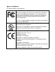
Agency Compliance This product complies to the following: CFR 47 Part 15, Class A Digital Device This device complies with Part 15 of the FCC Rules. Operation is subject to the following two conditions: 1) This device may not cause harmful interference, and 2) this device must accept any interference received, including interference that may cause undesired operation. This Class A digital apparatus complies with Industry Canada ICS003 class A requirements.
Table of Contents Agency Compliance ............................................................................................. 5 1. Safety Warnings and Cautions ........................................................................................ 1 General Safety Information ................................................................................... 1 2. Overview Workstation Series Overview ............................................................................... 3 w1110 Product Tour .
Table of Contents Important Notes: .........................................................................................................21 4. Operation Printer Modes ..................................................................................................... 53 Tear Mode ...................................................................................................................53 Present Sensor Mode .......................................................................................
1 Safety Warnings and Cautions The following Warnings and Cautions are used throughout this manual: Warning: Warnings alert you to possible safety risks. Caution: Cautions alert you to the potential for equipment damage. General Safety Information Caution: This product is intended for indoor use only. All service procedures should be done by properly trained and qualified service personnel.
1 | Safety The printhead heats during printing. Do not touch. Caution: Serious damage and bodily injury can result if this printer is exposed to liquids or foreign objects.
2 Overview Workstation Series Overview w1110 Product Tour The following illustrations show some of the features and available options for the printer. Figure: 2 - 1 Front View - w1110 2 3 4 5 1 1. Cover Latch Release 2. Stop/Resume 3. Power LED (Green) 4. Error LED (Red) 5.
2 | Overview Figure: 2 - 2 Rear View - w1110 1 2 3 4 5 1. Power Switch 3. Reset Button 2. DC Power Inlet 4. USB 2.0 Port 5.
Overview | 2 Figure: 2 - 3 Media Area 1 2 3 3 4 5 8 6 9 7 1. Printhead 6. Right Core Adapter 2. Upper Top-of-Form Sensor 7. Right Media Support Bracket 3. Cover Latch 8. Lower Top-of-Form Sensor 4. Left Media Support Bracket 9. Platen Roller . 5.
2 | Overview Options Figure: 2 - 4 Peel and Present 1 2 1. Peel Bar 2. Present Sensor Figure: 2 - 5 Serial Interface 1 1.
Overview | 2 Standard Features The thermal printer has the following standard features: Table 1: Standard Features Features Descriptions Max Print Speed 4 IPS / 102 mmps Resolution 300 dpi / 11.8 dpmm Memory 32MB Flash (4MB User Space) / 32MB DDR2 RAM Printer Type Direct Thermal Media Supply Double-sided Top-of-Form Sensor • Roll-fed • Die-cut • Continuous Labels: (5” [127mm] roll max diameter on 1.0” and 1.5” [25.
2 | Overview Features Descriptions Printer Driver Supported Operating Systems Operating Temperature • Windows XP • Windows Vista • Windows 7 • Windows 8 32°F (0°C) to 104°F (40°C) Options The following options are available: • Peel and Present • Serial Interface • Non-US Power Cords Unpacking the Printer Upon receiving the printer, verify the box is undamaged.
Overview | 2 Specifications Print Characteristics Table 2: Print Characteristics Variable Specifications Print Resolution 300 dpi (11.8 dpmm) Max Print Width 4.16” (105.7 mm) Max Print Speed 4 ips (102 mmps) Max Feed Speed 4 ips (102 mmps) Max Back-up Speed 4 ips (102 mmps) Media Width Range* 0.75” - 4.33” (19 mm - 110 mm) Media Thickness Range* 0.003” - 0.008” (0.076 mm - 0.20 mm) Print Length Range .25” - 30” (6.35 mm - 762 mm) *Media wound out.
2 | Overview Minimum System Requirements Supported Operating Systems Windows XP - x86 & x64 Windows Vista - x86 & x64 Windows 7 - x86 & x64 Windows 8 Configuration Utility Table 6: Configuration Utility Minimum System Requirements Minimum System Requirements Processor / Speed 500 MHz processor Supported Operating Systems Windows XP - x86 & x64 Windows 7 - x86 & x64 Windows 8 RAM 256MB Hard Drive Space 15MB Minimum Screen Resolution 800 x 600 .NET Framework 3.
3 Connections and Setup Connections Power To connect the printer to a viable power source, please follow the steps below. Caution: Ensure the printer power switch is off before connecting the AC power and data/network connectivity cables to the printer. Caution: Adhere to all environmental requirements when installing and using the printer. Use of the product in an unsuitable environment may affect print quality and the durability of the printer and may void the manufacturer’s warranty. 1.
3 | Connections and Setup Media Loading The w1110 printer supports either a 1” core or a 1.5” core paper roll. The core adapters can be removed, rotated and reinstalled depending on the desired core size. Please consult your reseller to obtain the appropriate media. 1. Lift the cover latch release and open the cover. 2. Verify the core size for the paper roll being used and select the appropriate core adapter side. a.
Connections and Setup | 3 Note: Ensure the core adapters have snapped into place. 3. Slide the media support brackets outward and place the paper roll between them. Note: The paper must be wound out. Figure: 3 - 2 Paper Roll Installation 4. Release the media support brackets ensuring the core is secured by the core adapters.
3 | Connections and Setup 5. Route the paper under the support bracket guides. Figure: 3 - 3 Support Bracket Guides Left Guide Right Guide 6. Close and latch the printer cover. 7. Feed the paper to find top-of-form. Note: When installing new media, perform a paper calibration to ensure the printer finds the top-of-form. Media Loading - Peel and Present The peel and present option allows for the media labels to peel at the peel bar while the label backing routes away from the labels.
Connections and Setup | 3 1. Open the peel and present sub-assembly. a. Rotate the peel and present sub-assembly forward. Figure: 3 - 4 Peel and Present Assembly 2. Load the media into the support bracket and the core adapters. 3. Remove the enough labels to expose at least 6” of backing. Insert the backing behind the roller of peel and present sub-assembly until it appears underneath.
3 | Connections and Setup Note: Be sure there are no labels attached to the backing that is routed behind the peel and present sub-assembly. Figure: 3 - 5 Media Backing Label Backing 4. Pull the label backing tight to ensure proper tension of the label backing. 5. Hold the backing tight and close the peel and present sensor assembly. 6. Close and latch the printer cover. 7. Feed the paper to find top-of-form. Note: Peel and present mode is enabled through the configuration utility.
Connections and Setup | 3 Control Panel The control panel consists of the two (2) main buttons on the printer cover, two (2) LEDs on the printer cover and the reset button on the back of the printer. All three are used to perform certain printer functions. LEDs The green and red LEDs may blink during the operation of the printer. There are functions of the printer where the blinking lights can be used to interpret the printer’s state. A slow blink is considered a repeating blink that lights for 0.
3 | Connections and Setup Buttons The operation of the buttons consists of long or short presses depending on the operation being performed. A button pressed for three (3) or more seconds is considered a long press. A button pressed for less than three (3) seconds is considered a short press. The Stop/Resume button is positioned on the left side of the printer’s control panel and the Feed/Cancel button is positioned on the right side.
Connections and Setup | 3 Sensor Calibration Sensor calibration is set during the manufacturing process and should only need to be performed after upgrading the printer’s software. This is indicated by the red LED blinking slowly after power-up. 1. Remove the paper from the printer. 2. Close and latch the printer cover. 3. Press the Reset, Stop/Resume, and the Feed/Cancel buttons together with one short press. Note: The green LED will have a fast blink sequence.
3 | Connections and Setup Print Driver Installation Overview This installation should be executed only on a computer where a pw Series printer driver is not currently installed or one that the driver have been completely removed. The Windows driver is located on the Accessories CD-ROM included with the printer. For the latest version please visit our web site at http://www.datamax-oneil.com Installing the Windows Driver: 1.
Connections and Setup | 3 6. Check the “Install printer drivers” radio button then click ‘Next’ and follow the on-screen instructions to install the driver. 7. When prompted, select your printer from the list, (i.e. Datamax-O’Neil w1110). Continue to follow the on-screen instructions to install the driver. Important Notes: The Windows driver functions the same as any other Windows printer.
3 | Connections and Setup Workstation Series User’s Guide 22
4 Operation Printer Modes The w1110 features three (3) modes: • Tear Mode • Present Sensor Mode • Pause Mode The modes are set in the printer’s configuration utility. Tear Mode Tear mode is used for most common print jobs and is the default mode for the printer. This mode is always used when Present Sensor Mode and Prompt Mode are not needed. To pause a batch print job, select the Stop/Resume (left) button with a short press and the printer will stop printing at the next label.
4 | Operation To continue the print job, select the Stop/Resume button. The print job can be canceled by selecting the Feed/Cancel (right) button with a long press. The green LED will illuminate with a solid light indicating the printer ready state.
Operation | 4 To print the System Report, select the Reset button and the Feed/Cancel (right) button with a short press.
4 | Operation • Auto Option Detect • Auto Present Distance • Auto Speed Adjust Adjustment Settings • Present Distance Adjust • Vertical Adjust • Horizontal Adjust • Darkness • Contrast Calibration Settings • Paper Threshold • Gap/Mark Threshold • TOF Gain To print the Settings Report, select the reset button and the Stop/Resume (left) button together with a short press. Webpages Webpages provide a printer configuration interface for the user.
5 Cleaning and Maintenance Overview To maintain good print quality and increase printhead life, proper cleaning should be routinely performed using factory-approved cleaning supplies. Caution: A contaminated printhead can cause premature printhead failure. Caution: Failure to clean the printhead as detailed in this manual could void the printhead manufacturer’s warranty. Intervals The printhead should be cleaned whenever a roll of labels is replaced or every 650 inches printed.
5 | Cleaning and Maintenance Workstation Series User’s Guide 58
6 Troubleshooting LED Indicators The printer LEDs are also used to indicate errors and warnings. Refer to the following chart: Table 1: LED Indicators Action Green LED Red LED Warning Not affected by Warning Slow Blink Error Off Solid Control Mode Short Blink with a Pause Not affected by Control Mode Notes Only applies when printer is in configurator session Printer is not operational during this time 0.1 seconds on and 2.
6 | Troubleshooting Errors Description PRESENT SENSOR HARDWARE Present sensor hardware fault HEAD UP Printing or feeding with the cover open Note: To clear errors, open the printer cover fully and then close and latch it.
Troubleshooting | 6 Symptom Causes Solutions Paper Sensor Blocked Adhesive, dirt or remnants of a label may be covering the sensor. 1. Clean the debris from the sensor. 2. Perform “Calibrate Sensors” calibration. Paper Calibration No Top-of-Form Found The main controller board may be faulty. Contact your technical support representative. The Top-of-Form sensor failed the “Calibrate Sensors” calibration due to a faulty sensor. Contact your technical support representative.
6 | Troubleshooting 2. Load the media according to the instructions in the Setup section. Note: Verify that the paper is properly exiting the printer. 3. Print a Quality Label from the configuration utility or the printer control panel buttons. 4. Examine the print quality. Note: Some imperfections can be caused by a contaminated printhead. Clean the printhead and reprint the label. Symptom Possible Solutions No Print or Poor Print Quality Verify the proper media is being used.
7 Appendix A Symbol Sets The following Symbol Sets are available: Table 1: Symbol Sets Number Symbol Sets 0 PC-8 1 Roman-8 2 Roman-9 3 ISO-L1 4 ISO-L2 5 ISO-L4 6 ISO-L5 7 ISO-L6 8 ISO-L9 9 PC-775 10 PS MATH 11 MATH-8 12 PI FONT 13 MS PUBL 14 PC-8 DN 15 PC-850 16 PC-852 17 PC-858 18 PC-8 TK 19 PC-1004 20 WIN L1 21 WIN L2 22 WIN L5 23 WINBALT 24 DESKTOP 25 PS TEXT 26 LEGAL 27 ISO-4 63 Workstation Series User’s Guide
7 | Appendix A Number Symbol Sets 28 ISO-6 29 ISO-11 30 ISO-15 31 ISO-17 32 ISO-21 33 ISO-60 34 ISO-69 35 WIN 3.
Appendix A | 7 Font Escape Sequence CG Omega ((s1pv0s0b4113T CG Omega Italic ((s1pv1s0b4113T CG Omega Bold ((s1pv0s3b4113T CG Omega Bold Italic ((s1pv1s3b4113T Garamond Antiqua ((s1pv0s0b4197T Garamond Kursiv ((s1pv1s0b4197T Garamond Halbfett ((s1pv0s3b4197T Garamond Kursiv Halbfett ((s1p
7 | Appendix A Font Escape Sequence Vera Regular Mono ((s0ph0s0b23410T Vera Italic ((s0ph1s0b23410T Vera Bold ((s0ph0s3b23410T Vera Bold Italic ((s0ph1s3b23410T CG Triumvirate ((s1pv0s0b92244T CG Triumvirate Condensed Bold ((s1pv4s3b92250T LinePrinter ((s0p16.67h8.
Appendix A | 7 Barcode ID Type Length Valid ASCII Characters, decimal value representation 1091 MSI Plessey Mod 10 1-55 0-9 1100 Code 93 1-107 ASCII 0x20-0x7F 1110 HIBC Code 93 1-36 0-9, A-Z, $,%,+,-,.,/,space 1111 HIBC Code 128 1-36 0-9, A-Z, $,%,+,-,.