
Operator`s manual


88 A-Class
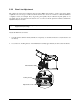
3. Turn the Adjustment Screws counter-clockwise to bring the burn line forward, beyond the vertex of
the platen roller.
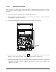
4. Print a Validation Label; see Section 4.4.4. (The label should have a light, uneven appearance.)
5. Tighten the Locking Screws until they are ‘snug’ (that is, tight enough to remove any play in the
printhead assembly, yet loose enough to allow the Adjustment Screws to move the printhead).
6. Turn each
Adjustment Screw clockwise about a ¼ turn (or 1/8 a turn for finer adjustments, see note
below). (Typically, a thicker media requires a slight forward adjustment, while a thinner media
requires a backward adjustment). Print another Validation Label and examine the print quality.
Repeat this step until the print is produced with even contrast and acceptable quality across the width
of the label.
Note: When the Locking Screws are ‘snug’, turning the Adjustment Screws counter-clockwise will NOT
move the printhead outward. If you have adjusted the printhead too far inward, restart the entire
procedure.
7. Tighten the Locking Screws. Print a final Validation Label to verify the adjustment.