
Operator`s manual


A-Class 147
7. Slide the card back into the printer; secure it in place with the two screws.
8. Connect an applicator interface cable to J2 (and, if needed, connect a serial cable to J1).
9. Connect the power cord and turn ‘On’ the printer.
10. Using the Menu System, configure the operational settings of the GPIO Port to meet the requirements
of your applicator system (see Section 4.2.4).
If needed, also configure the operational settings of the Aux Serial (Serial Port B) to meet the
requirements of your system (see Section 4.2.6).
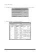
11. If desired, confirm your programmed settings by printing a GPIO Signal Info Label (see Section
4.2.7). This completes the setup of the Applicator Interface Card.
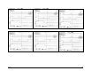
Applicator Timing Signals
During a typical print cycle, DRDY (Data Ready) will become active when a label is waiting to be
printed. After the SOP (Start of Print) signal is received by the printer, printing will begin. For
synchronization with the print cycle, the EOP (End Of Print) signal indicates the completion of the print
process. Screen shots of timing signals for the GPIO Interface are presented below. All sample shots were
taken while printing a two-count label batch. The variable parameters were as follows:
Present Distance = 0 or .25"
Start of Print = ‘On/Off’ (pulsed) or ‘On’
Imaging Mode = Single (stops) or Multi (keeps going)
All other parameter notes accompany the respective screen shot.
Note: The printing process is not complete until the label reaches its present distance (if programmed) because
a label that is presented requires addition positioning (backup) and, therefore, more time.