Operator’s Manual Corporate Headquarters 4501 Parkway Commerce Blvd.
Copyright Information: CG Triumvirate is a trademark of Agfa Corporation. CG Times based upon Times New Roman under license from the Monotype Corporation. Windows and Windows NT are trademarks and Microsoft is a registered trademark of Microsoft Corporation. NetWare and Novell are registered trademarks of Novell, Inc. Ethernet is a registered trademark of Xerox Corporation.
Agency Compliance and Approvals: C US UL1950 Information Technology Equipment C22.2 No. 950-M93 Listed EN60950 For 230 Volt Operation (Europe): Use a cord set, marked “HAR,” consisting of a min H05VV-F cord which has a minimum 0.
Important Safety Instructions: The exclamation point within an equilateral triangle is intended to alert the user to the presence of important operating and maintenance instructions in the literature accompanying this unit. This unit has been carefully designed to provide years of safe, reliable performance.
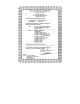
Contents Printer Overview 1.0 1.1 1.2 About the Printer..................................................................... 1 1.0.1 Standard Features................................................... 2 1.0.2 Optional Features ................................................... 2 Option Installation................................................................... 6 Hardware Components .......................................................... 7 Getting Started 2.0 2.1 Unpacking the Printer............
Using the Front Panel 4.0 4.1 4.2 4.3 Operation.............................................................................. 29 4.0.1 Ready Mode: Normal Operation ........................... 29 4.0.2 Menu Mode: Configuration.................................... 30 4.0.3 Quick Test Mode: Print Test Labels...................... 31 4.0.4 Indicator Lights ...................................................... 32 4.0.5 LCD........................................................................ 32 4.0.
5.2 5.3 5.4 5.5 Printhead Replacement........................................................ 79 Maintenance Schedule......................................................... 80 5.3.1 Cleaning the Printhead.......................................... 81 5.3.2 Cleaning the Platen Roller .................................... 82 5.3.3 Cleaning Interior and Exterior Surfaces................ 83 Application Program Updates .............................................. 83 5.4.1 Updating from the Ready Mode.......
Appendix E Menu System Multi-Language Support ...................................... 121 Advance File Handling Information............................................. 124 Appendix F Saving a Configuration File ......................................................... 127 Warranty Information ...................................................... 129 Glossary .................................................................................
Printer Overview 1.0 About the Printer Congratulations on your purchase of an I-Class printer. The I-Class family, hereafter referred to as ‘the printer’, blends the rugged durability of die-cast construction with state-of-the-art electronics and user-friendly features to redefine the standard in industrial thermal printers. This manual provides all the information necessary for everyday printer operation.
1.0.1 Standard Features This printer offers the following standard features: I-Class Standard Features Listing Feature Printhead Density (Dots Per Inch) Direct Thermal Printing On-Demand and Batch Printing Rotating Media Hub Media Tear Bar Fan-fold media capability Flash memory SDRAM RS-232 interface port IEEE 1284 Compliant parallel interface port Liquid Crystal Display EFIGS (multi-language display and configuration label support) AGFA Scalable font engine 1.0.
DMXNet The DMXNet Print Server Card is an internal Network Interface Controller (NIC) that enables the printer to provide Ethernet connectivity. Features include: ¾ ¾ ¾ ¾ ¾ ¾ ¾ ¾ ¾ ¾ ¾ ¾ ¾ ¾ ¾ Automatic selection of 10Base2 (Thinnet) or 100BaseT Fast Ethernet connection. Integral HTTP Server to allow monitoring and management from a standard Web browser program. Peer-to-Peer (serverless) discovery and printing from Windows 95/98/ME/XP or Windows NT/2000 workstations without a Novell file server present.
External Media Rewinder (specify voltage requirement when ordering) A precision-crafted, bi-directional rewinding mechanism with device-dependant features: ¾ DMXREW1 – accommodates 1 to 4-inch (25 to 101 mm) diameter cores; accepts a maximum label width of 4.5 inches (114 mm); and, rewinds to a 8-inch (203 mm) maximum outer diameter at 10 inches per second. ¾ DMXREW2 – accommodates 3-inch (76 mm) diameter cores; accepts a maximum label width of 9.
readability of printed bar codes. Minimum bar code “X” dimension is 10 mils; maximum width is 4 inches (101 mm). Peel and Present Mechanism (requires the Internal Rewind option) An output control device that automatically separates printed labels from the backing material and allows subsequent printing to occur only after the removal of a previously printed label. Minimum label length is 1.5 inches (38 mm).
1.1 Option Installation The following table lists the available options and the recommended qualification level of the installer. For detailed information concerning a specific option, contact your dealer or Datamax Technical Support.
1.2 Hardware Components The following drawing highlights the user-assessable components of the printer. Items denoted with an asterisk (*) are optional equipment.
8 I-Class
Getting Started 2.0 Unpacking the Printer Inspect the shipping container(s) for damage; if evident, immediately notify the shipping company to report the nature and extent of the damage. The printer has been carefully packaged to avoid damage during transit. In order to operate the printer, you will need to remove the tape and foam placed there for shipment. Complete the following steps prior to connecting power or attempting to load media. n With the arrow on the box pointing up, open the box.
2.0.1 Inspection After removing the printer from the packaging material, check the contents of the package. In addition to this manual, the following items should be included: ¾ Printer ¾ Power Cord ¾ Accessories CD ¾ Any special or additionally purchased items. 2.0.2 Additional Requirements The following items are necessary to produce labels. Contact your dealer or a customer support representative for advice on which media and software may best suit your needs.
2.1 Media and Ribbon Selection The following is a limited overview of media characteristics. For complete information and advice regarding your specific application needs, always consult a qualified media specialist or a Datamax Media Representative. Media Selection – Direct Thermal Consider three important factors when selecting direct thermal stock: The abrasive qualities of the material that covers the thermal reactive layer of the paper.
resulting in a darker image. Conversely, if the image is too dark, reduce this value. The final method is to change the ‘Print Control / Print Speed’ menu setting (also selectable as ‘Print Speed’ in most software programs). Changing the print speed changes the amount of time the media is under the printhead. Slower speeds allow more time and control for energy transfer, while faster speeds will increase throughput, but may require higher heat settings.
Setting Up the Printer 3.0 Installation This section explains how to connect the printer, and load it with media and ribbon. ; Note: When connecting the AC Power Cord or interface cables to the printer, ensure the Power On/Off Switch is in the ‘Off’ position. n Place the printer on a firm, level surface. o Turn ‘Off’ the Host Computer and ensure that the Power Switch on the Printer is in the ‘Off’ position.
3.0.1 Communications Using a data detection process, the interface selection occurs automatically in the printer. At power-up, the printer begins monitoring the interface ports for activity. When the host transmits data, the printer port detecting this data is set ‘active’ and remains active as long as data flow continues. Once the incoming (received) data flow stops and the Host Timeout Value (see Section 4.1.6) is exceeded, the detection process will be repeated.
Serial Interface Cable Listing (all models, except as noted) Null Modem (MXM) “PC” (DB9P) to Printer Part Number 556000 Part Number 556001 For connection to other DCE equipment. Flow control is only Xon/Xoff. For connection to a PC compatible with DB9P communication ports. Flow control can be either Xon/Xoff or CTS/DTR. “PC” (DB25P) to Printer RS-422 Connection* Part Number 556002 Part Number N/A For connection to a PC compatible with DB25 communication ports.
When finished with the self-tests, the LED blinks, and may blink again after printer initialization is completed. Amber LED – generally indicates job activity. When receiving print jobs over the network, the amber LED blinks; it remains ‘Off’ during inactivity. Error Conditions: Combinations of blinking LEDs – 1 to 7 amber blinks followed by 1 to 12 green blinks – indicate various hardware failures. See the DMXNet Resource Manual for more information.
3.1 Loading Media Begin loading as follows: n Raise the Access Cover. o Rotate the Printhead Latch forward and raise the Printhead Assembly. p Slide the Media Guide out away from the frame and then lower it to the down position. q If using roll media, the Media Hub can accept 3.0-inch (76mm) and 1.5inch (38mm) cores. To use 1.5-inch cores, first slide off the 3 Inch Hub by grasping and then pulling it firmly outward. r Proceed according to the type of media you are using: go to Section 3.1.
3.1.1 Roll Media This loading method is for roll type media applications. To load: n Slide the Roll Media onto the Media Hub until it rests against the Backstop. o Route the media as shown: under the Media Idler, through the Media Sensor, then out the front of the printer. p Raise and slide the Media Guide over until it rests lightly against the edge of the media. q Position the Media Sensor; see Section 3.2. r If your application uses thermal transfer media, load ribbon (see Section 3.
3.1.2 Fan-Fold Media This loading method is for tag and fan-fold type media applications. To load: n Bring the media in through the Bottom or the Rear Media Slot. (If using reflective stock, ensure that the mark is facedown.) o Depending upon the entry point, route the media as shown: if through the Rear Media Slot, route the media over the Media Hub; or, if through the Bottom Media Slot, route the media over the Media Rewind Hub.
3.2 Media Sensor Adjustment The Media Sensor needs to be positioned so that the printer can detect the presence of media and the top-of-form (except for continuous stock, where the TOF is set through programming; see Label Length, Section 4.1.2). To adjust: n With media loaded, as described in Section 3.1.1 or 3.1.2, grasp the Slide Tab and move the Sensor Eye Mark into position over media according to the table below. o If loading media, return to the media loading instructions.
3.3 Loading Ribbon Ribbon is required with thermal transfer media. Depending upon the type of Ribbon Supply Hub (see the next page for examples), the printer must use either ribbons with the ‘coating side in’ or ribbons with the ‘coating side out’. To load: ; Note: Using a ribbon that is slightly wider than your media (and liner, if any) will help protect against printhead wear.
; Note: Directional Arrows near the Ribbon Supply Hub indicate the correct ribbon route. Ribbon types are available with the ink (coating) layer wound ‘in’ or ‘out’. These types are NOT interchangeable for use with the printer.
3.4 ☞ Quick Media Calibration When ‘Uncalibrated’ is displayed, follow the Media Sensor Calibration procedure in Section 5.0. At the factory, the printer is calibrated to sense a wide range of media types. Quick Media Calibration fine-tunes the media sensor for your gap, notch or reflective media application. Note that this is not required if you are using continuous media. Perform this calibration during initial set-up or after changing your media type.
3.5 Outputting Labels In addition to directly outputting labels from the printer, there are several optional output configurations available. 3.5.1 Rewinding With the Internal Media Rewinder option, the printer can wind the printed labels and backing material. To rewind labels: ; Note: When winding labels, do not allow the outer diameter of the roll to exceed 6 inches (154 mm) on the Media Rewind Hub. n Remove the Front Fascia. o Remove the Tear Plate by first removing the Thumbscrew.
s Route the media back to the Media Rewind Hub, as shown below. t Insert the leading edge into a Slot on the Media Rewind Hub then insert the Media Clip into a Slot to secure it in place. u Position the Rewind Retainer lightly against the edge of the media on the Media Rewind Hub. Tighten the Thumbscrew to secure the retainer in place. v Manually rotate the Media Rewind Hub to remove any slack in the media. Close the Access Cover. Removal: Remove the Rewind Retainer and Media Clip.
3.5.2 On-Demand Dispensing When equipped with the Peel and Present option, labels are dispensed then separated automatically from the liner for immediate application. n With the Peel and Present Mechanism installed on the printer, pull outward on the Latch and allow the Roller Bracket to swing forward. o With media loaded as described in Section 3.1, press the FEED Key to advance approximately 20 inches (51 cm) of media. Remove all of the labels from the backing material.
r If installed, remove the Media Clip and the Rewind Retainer from the Media Rewind Hub. Route the Backing Material around the Media Rewind Hub, as shown. s Insert the leading edge into a Slot on the Media Rewind Hub then insert the Media Clip into a Slot to secure it in place. t Position the Rewind Retainer lightly against the edge of the backing on the Media Rewind Hub. Tighten the Thumbscrew to secure the retainer in place. u Manually rotate the Media Rewind Hub to remove any slack in the media.
3.5.3 Cutting When equipped with a Cutter, cut labels are dispensed automatically from the printer. To load media on a cutter equipped printer n Ensure the leading edge of media is clean, straight and firmly attached to the liner. o Load media according to Section 3.1, except route the media out through the Opening of the Cutter Assembly. ☞ 28 For label cutting, ensure that the Cutter has been enabled; see Section 4.1.4.
Using the Front Panel 4.0 Operation The front panel is comprised of three indicator lights, a Liquid Crystal Display and five mode-dependant keys. The selectable modes (Ready, Menu and Quick Test) and the related functions of the printer keys are detailed below. 4.0.1 Ready Mode: Normal Operation (Ready Light ‘On’) n The PAUSE Key temporarily suspends printing. Pressing it again will return the printer to normal operation. o The FEED Key advances one label, and clears any corrected faults.
4.0.2 Menu Mode: Configuration (Ready Light ‘Flashing’) n The DOWN ARROW Key scrolls to the previous menu item on the same menu level. It also decrements numerical values in most menu selections. o The UP ARROW Key scrolls to the next menu item. It also increments numerical values in most menu selections. p The ENTER Key selects the function, item or displayed value. It also moves between selections within multiple parameter fields.
4.0.3 Quick Test Mode: Print Test Labels ; Note: The Quick Test Mode functions are disabled while processing data from communications interfaces until the Host Timeout value expires. n The DOWN ARROW Key scrolls to the previous test function. o The UP ARROW Key scrolls to the next test function. p The ENTER Key will change the selected test label quantity of 2, 100, 1000, or 9999 (except the ‘Configuration Label’, quantity of one). Holding down the key scrolls quantities.
4.0.4 Indicator Lights n ‘On’ indicates that the printer is powered ‘On’ and, after initialization, it indicates the Ready Mode. ‘Slow Flashing’ indicates Menu Mode. ‘Fast Flashing’ indicates data is being received and processed. o ‘On’ indicates a ‘Paused’ condition. p ‘Slow Flashing’ indicates a Warning. ‘Fast Flashing’ indicates a Fault. See Section 6.1 for a listing of associated messages. 4.0.
4.0.6 Resetting the Printer Depending upon the method used, there are three reset levels possible: 4.0.6.1 Soft Reset To reset the printer and clear any temporary host settings: With the printer ‘On’, press and hold the CANCEL Key for approximately four seconds. 4.0.6.2 Level One Reset To return the printer to the factory default settings or, if saved, to restore the Factory Setting File: n Turn ‘Off’ the printer.
4.1 The Menu System Printer operation can be controlled through the user interface, allowing the operator access to these six menu system branches: Media Settings Print Control Printer Options System Settings Communications Diagnostics While in the menu system, the current selection will be indicated with an asterisk (*) next to the displayed item on the LCD. Selections designated with a section symbol (§) will require a printer reset before becoming effective.
4.1.1 Entrance and Exit Prompts With ‘Ready’ displayed on the LCD, press the Key to enter Menu Mode. ; Note: While in Menu Mode, the printer will stop processing new DPL (or bitmapped) data. MENU MODE ENTER PASSWORD 0000 KEEP HOST CHANGES? ENTER = YES SAVE CHANGES? ENTER = YES Depending upon the configuration of the printer, the following Entrance and Exit Prompts may be displayed when accessing or leaving the Menu System. You are attempting to enter Menu Mode.
4.1.2 Media Settings MEDIA TYPE Selects the printing method. DIRECT THERMAL For use with heat sensitive media. THERMAL TRANSFER For use with media requiring a ribbon to create an image. SENSOR TYPE GAP CONTINUOUS REFLECTIVE LABEL LENGTH 04.00in (0-99.99) Selects the top-of-form (TOF) sensing method for the media. The printer recognizes the TOF by sensing gaps in the media. No TOF sensing. The LABEL LENGTH setting determines the length.
4.1.3 ☞ Print Control Refer to Section 2.1.1 for detailed information on print quality controls. HEAT 10 (0-30) Controls the ‘burn-time’ of the printhead. This is the equivalent of Heat Setting on most label software programs. PRINT SPEED Controls the rate of label movement during the printing process; see Appendix C. FEED SPEED Controls the rate of label movement between printing areas; see Appendix C.
Print Control (continued) CUSTOM ADJUSTMENTS DARKNESS XX (1-64) ROW ADJUST XXX DOTS (-100 Æ 100) COLUMN ADJUST XXX DOTS (0-128) PRESENT ADJUST XXX DOTS (0-128) 38 These factory adjustments independently change the listed parameters to finely tune the printer and compensate for slight mechanical differences sometimes evident if multiple printers share label formats. In addition, each of the following adjustments has no factory default setting and restoring factory defaults will not affect these settings.
4.1.4 Printer Options MODULES PRINT DIRECTORY PRINT FILE FORMAT MODULE DELETE FILE PACK MODULE PRESENT SENSOR Memory available for user storage of graphics, fonts and label formats. (The physical presence of the respective memory module must be detected to show the function selections in the menu system. See Appendix C for a listing of all possible modules.
Printer Options (continued) CUTTER ENABLED Used to cut media into separate labels. (The physical presence of a device must be detected to show the ENABLE/DISABLE selections.) Enables cutting. DISABLED Disables cutting. NOT INSTALLED No Cutter is detected. SCANNER NOT INSTALLED MODE PICKET FENCE DISABLED BARCODES Used to check the bar codes on the labels. (The physical presence of a device must be detected to show the menu selections.) No Scanner is detected.
Printer Options (continued) BARCODE COUNT 00 (00-99) REDUNDANCY LEVEL Used to set the specific number of barcodes to be read on the label. 00 selects AUTO Mode, allowing a variable number of barcodes to be read per label format. AUTO Mode should not be used with imaged (bitmapped) barcodes or with certain bar code addendums as shown in Appendix B. Used to ensure the data integrity of the bar code.
Printer Options (continued) GPIO PORT DISABLED Model dependant option used to interface the printer to an external controlling device (see Appendix D). Input control signal is required to print a label. Disables the GPIO. APPLICATOR Enables the GPIO for a Label Applicator. BARCODE VERIFIER Enables the GPIO for the Barcode Verifier. GPIO DEVICE ACTIVE HIGH Programmable signal input controlling the Start of Print (SOP). Signal must go high at SOP. ACTIVE LOW Signal must go low at SOP.
4.1.5 System Settings CONFIGURATION FILE RESTORE AS CURRENT SAVE SETTING AS DELETE FILE Options for storage and recall of printer configuration files. See Appendix F for details. Provides a list of available configuration files. Selecting a file from the list causes a printer reset; afterward, the printer is configured according to the activated file. Saves the entire effective configuration of the printer to a file. Unique names with up to nineteen characters are possible.
System Settings (continued) DOUBLE BYTE SYMBOLS UNICODE When equipped with the ILPC option, this selects the code page used to print double byte fonts unless otherwise specified in DPL; see the I & W Class Programmer’s Manual for details. Unicode (including Korean) BIG 5 Government Bureau Industry Standard; Chinese (PRC) Taiwan encoded JIS Japanese Industry Standard SHIFT JIS Shift Japanese Industry Standard EUC Extended UNIX Code GB TIME AND DATE Allows the user to set Time and Date.
System Settings (continued) CONFIGURATION LEVEL PRINTER KEY To upgrade the application program (resident software) version of the printer, the hardware and software compatibility levels must match for the update to be accepted. This information is displayed here; it is also printed on a configuration label.
System Settings (continued) SET FACTORY DEFAULTS SET FACTORY DEFAULTS Parameters in this menu listing with the ‘’ symbol are the designated defaults. Overwrite the current settings with the factory default settings or, if selected, will restore the Factory Setting File. ; Note: The reset will be automatic. If no Factory Setting File is used, all menu settings will be restored except CUSTOM ADJUSTMENTS, and the media and ribbon sensor calibrations.
System Settings (continued) PAUSE MODE ENABLED DISABLED PEEL MODE ENABLED DISABLED When enabled, suspends printing between each label until the PAUSE Key is pressed. Requires an operator press the PAUSE Key after each label. The printer completes label batch without pausing between labels. Specifies that a Feed operation be prevented when the label is presented and not removed, or if the printer is to wait for the GPIO start of print signal. Feed is inhibited according to the above criteria.
System Settings (continued) ; Note: As indicated, the following menu selections will only appear according to the model of your printer. PLUS EMULATION ENABLED 48 I-4206, I-4208, & I-4212 Models DISABLED This instructs the firmware to process specific DPL data as would the Prodigy Plus® printer without all of the variations. The calculated Column position based on 200 DPI using a 203 DPI printhead.
System Settings (continued) ; Note: As indicted, the following menu selections will only appear according to the model of your printer. ALLEGRO EMULATION DISABLED DISABLED 203 DOTS PER INCH DPI EMULATION 300 DOTS PER INCH 203 DOTS PER INCH I-Class For users who want to print DPL files intended for a 203 or 300 DPI printer. Label formats interpreted as intended for 600 DPI. Label formats interpreted as intended for 300 DPI. Label formats interpreted as intended for 203 DPI.
System Settings (continued) COLUMN EMULATION 203 DOTS (180-203) SOP EMULATION 110 (PRODPLUS) Enables the O and f print positioning commands to allow backward compatibility with label formats designed for other printers. (When changing these values, the printer will automatically feed two labels to setup the new print position.) Emulates the Prodigy Plus® printer. 220 (ALLEGRO) Emulates the Allegro® printer. 250 (PRODIGY) Emulates the Prodigy™ printer. DISABLED No emulation, position.
System Settings (continued) ENGLISH Selects the language in which the menu system messages and configuration label are shown. Only languages that are resident will be available. English FRANCAIS French ITALIANO Italian DEUTSCH German ESPANOL Spanish USER DEFINED User defined, downloaded language(s). MENU LANGUAGE FAULT HANDLING LEVEL 1 2 When a faulted condition (ribbon or paper out, failed bar code, etc.
System Settings (continued) VOID DISTANCE 0.25in (0-2.00) RETRY COUNT 1 (0-3) The distance to backup on the defective label and the font size in which to print the VOID text. Establishes the number of retries the printer will attempt to reprint a defective label after it has been voided. If the last label printed has been voided, it will be reprinted after correcting the problem. After the last retry, the printer will stop and display a fault message.
4.1.6 Communications SERIAL PORT A BAUD RATE Controls the communications settings for Serial Port A. Determines the serial communication rate. BOTH SOFTWARE HARDWARE NONE PARITY 38400 bits per second 28800 bits per second 19200 bits per second 9600 bits per second 4800 bits per second 2400 bits per second 1200 bits per second Sets the data flow control (handshaking) method. Uses both handshaking methods. XON/XOFF CTS/DTR No flow control is used.
Communications (continued) PARALLEL PORT A PORT DIRECTION UNI-DIRECTIONAL BI-DIRECTIONAL PARALLEL PORT B Controls the communications settings for Parallel Port A. Determines if messages are sent from the printer to the host via the parallel port. One-way printer communication. Enables IEEE operation. 1284 back-channel Same as Parallel Port A, for an optional Ethernet connection. If not present, this displays ‘NOT INSTALLED’ when accessed.
Communications (continued) Specifies the network gateway address the NIC Adapter should use. SNMPTRAP DESTINATION Selects the Network IP address where all SNMP Traps will be sent. If zeroed, no traps are sent. PROTOCOL The network protocols recognized by the NIC Adapter. NETWARE Allow the printer to be driven from an NDS Novell Print Queue. ENABLED Netware is enabled by default. GATEWAY DISABLED DISCOVERY Ignore the Netware protocol. Select this option if Netware is not needed.
Communications (continued) HOST SETTINGS Settings which affect all communications with a host. HOST TIMEOUT The number of seconds a communications 10 SEC (1-60) port must be idle before the printer may process data from a different port. This value is also used to “timeout” an image / label format download. CONTROL CODES Allows the operator to change the prefix of the software commands interpreted by the printer.
Communications (continued) HEAT COMMAND ENABLED Allows the user to disable the DPL Heat Command, providing compatibility with other DATAMAX printers. Normal printer operating mode. DISABLED DPL Heat Commands are ignored. The heat value is controlled via the menu setting; see Print Control, Section 4.1.3. SPEED COMMANDS Allows the user to disable the DPL speed commands (Print, Feed, and Reverse). Normal printer operating mode. ENABLED DISABLED I-Class DPL speed commands are ignored.
4.1.7 Diagnostics HEX DUMP MODE ENABLE DISABLE OPTIONS TESTING TEST PRESENT SENSOR TEST CUTTER PERFORM TEST 1 TIME Most commonly used for troubleshooting. Prints data and instructions received from the host rather than interpreting them as label formats; see Section 6.2. Prints raw ASCII data received from the host rather than executing the commands. Executes and prints label formats (normal operating mode). Tests currently installed options Performs a functional test of the Present Sensor circuitry.
Diagnostics (continued) SENSOR READINGS THR TRAN RIBM 24V Æ 255 255 255 255 Å PS HD RANK 255 255 255 RIBBON SENSOR LIMITS RIBBON ADC LOW HIGH 070 164 I-Class Analog Sensor readings are displayed. Live sensor values are displayed. View can be toggled with the FORWARD and REVERSE Keys. Maximum values are shown in this example: thermistor sensor, transmissive (gap) media sensor (TRAN is replaced with REFL when the SENSOR TYPE is set to ‘reflective’), ribbon sensor, 24 volt power supply sensor.
4.2 Display Messages The printer displays several different types of information (if not in the menu system or Quick Test Mode): ¾ User Prompts and Condition Messages (also see Section 4.1.1 for a listing of the Enter/Exit Prompts) ¾ Application and Boot Loader Updating Messages (see Section 5.4 and 5.5) ¾ Fault and Warning Messages (see Section 6.1) 4.2.1 User Prompts and Condition Messages User Prompts alert the operator to a required action.
User Prompts and Condition Messages (continued) Displayed Message Description Condition(s) Ready Mode. Normal operating mode. The printer is ready to receive and process label formats. A label is awaiting removal. The Present Sensor option is enabled and a label blocks the sensor. Remove the label to continue printing. SFBEZ SFNPWF!MBCFM TZTUFN JOJUJBMJ[JOH TZTUFN!SFTFU! JO!QSPHSFTT Normal power-up and Follows the ‘SYSTEM soft reset condition. RESET IN PROGRESS’ message after a reset or power-up.
4.3 Quick Test Mode This section explains the functions of the resident Quick Tests, accessible by pressing the Key on the Front Panel. ; Notes: (1) With the exception of the Configuration Label, all Quick Test labels require 4-inch (102mm) wide media to print the entire format. If using narrower media, change the Label Width setting (Section 4.1.2) to match your media’s width to avoid printing on the platen. (2) During any Quick Test, press the Key to stop printing.
4.3.2 Configuration Label The Configuration Label provides printer valuable database information, as detailed in Section 4.1. To print a Configuration Label: n Press the Key. o Use the Key to scroll to ‘Print Configuration’. p Press the Key to print. ; Note: The contents of this label may vary with the application version and printer model and equipped options. To capture all the information, use media at least 2 inches wide (51mm) with the Label Width setting matched accordingly (see Section 4.1.2).
4.3.3 Quick Ribbon Test Label The Quick Ribbon Test Label features a compliant picket-fence bar code that can be used to verify thermal transfer and print quality functions. To print a Quick Ribbon Test Label: n Press the Key. o Use the Key to scroll to ‘Ribbon Test Label’. p Use the Key to select a quantity; see Section 4.0.3. q Press the 64 Key to start printing.
4.3.4 Dot Test Pattern Label The Dot Test Pattern Label features patterns that exercise the thermal elements of the printhead to indicate its overall condition (see examples below). To print a Dot Test Pattern Label: n Press the Key. o Use the Key to scroll to ‘Dot Test Pattern’. p Use the Key to select a quantity; see Section 4.0.3. q Press the Key to start printing. Good Test Pattern Label: Even pattern consistency indicates correct printhead operation.
4.3.5 Validation Label The Validation Label is another useful tool for evaluating overall print quality. To generate a Validation Label: n Press the Key. o Use the Key to scroll to ‘Validation Label’. p Use the Key to select a quantity; see Section 4.0.3. q Press the 4.3.6 Key to start printing. User Defined Label The User Defined Label reprints the last format printed. The format can be any of the Quick Tests, a label from the host, or a label recalled from a memory module.
Adjusting and Maintaining the Printer 5.0 Media Sensor Calibration In addition to the Sensor Type selection, Media Sensor calibration ensures that each label is detected correctly and reliably. Perform calibration when the ‘Uncalibrated’ message is displayed. Two different methods are available to calibrate the printer: Standard and Advanced Entry. 5.0.1 Standard Calibration Standard Calibration is appropriate for most media types.
Standard Calibration (continued) Step 3 4 Operator Action Press the Key to enter the Media Settings menu. Press the Key and scroll to ‘Sensor Calibration’. 5 Press the Key. 6 Press the Key. Displayed Message NFEJB!TFUUJOHT NFEJB!UZQF Comme nt See Section 4.1.2 for menu layout. ! NFEJB!TFUUJOHT TFOTPS!DBMJCSBUJPO ! TFOTPS!DBMJCSBUJPO QFSGPSN!DBMJCSBUJPO Press the Key to abort this procedure. You are beginning the standard calibration procedure.
Standard Calibration (continued) Step 7 Operator Action Proceed according to your media type: Displayed Message TDBO!CBDLJOH QSFTT!BOZ!LFZ!!!=zzz? Die-cut stock: strip the Or, for reflective media: media from the backing and then reinsert it into TDBO!NBSL the sensor; adjust the QSFTT!BOZ!LFZ!!!=zzz? Sensor Eye Mark over the center of the backing. Notched stock: adjust the Sensor Eye Mark over the center of the notch.
Standard Calibration (continued) Step 9 Operator Action Observe the display. Displayed Message HBQ!NPEF DBMJCSBUJPO!DPNQMFUF Or, for reflective media: SFGMFDUJWF!NPEF! DBMJCSBUJPO!DPNQMFUF Comme nt The calibration was successful. See note below if another message was displayed. Or, for continuous media: ! DPOUJOVPVT!NPEF! DBMJCSBUJPO!DPNQMFUF 10 Exit upon successful calibration: Back out of the menu tree by repeatedly pressing the Key. If using gap or reflective media, press and hold the FEED Key.
5.0.2 Advanced Entry Calibration Advanced Entry Calibration is the alternate method for special-case media types. The procedure has two parts: 1) You must list the sensor readings for the label and TOF values using different algorithms. 2) From your list the best algorithm is chosen, new readings taken and those values entered. ☞ Advanced Entry Calibration will override all previous calibration settings; this method should be used only when Standard Calibration has failed.
Advanced Entry Calibration (continued) Step Operator Action 6 Press the Key to scroll to ‘Advanced Entry’. 7 Press the Key. Displayed Message TFOTPS!DBMJCSBUJPO BEWBODFE!FOUSZ BEWBODFE!FOUSZ TFOTPS!MFWFMT ! 8 Press the Key. BEWBODFE!FOUSZ TFOTPS!HBJO ! 9 Press the Key. Place the label under the Sensor Eye Mark and lower the printhead assembly.
Advanced Entry Calibration (continued) Step Operator Action 11 Proceed according to your media type: Die-cut stock: strip the media from the backing and then reinsert it into the sensor; adjust the Sensor Eye Mark over the center of the backing. Notched stock: adjust the Sensor Eye Mark over the center of the notch. Reflective stock: Adjust the Sensor Eye Mark over the center of the facedown black mark. Displayed Message HBJO!USBO!!!!!=zzz? +11!!!!!!!!)1!.
Advanced Entry Calibration (continued) Step Operator Action Displayed Message 12 From the data collected in Steps 10 and 11, where both the sensor readings are above 20, subtract each Label Value from the corresponding TOF Value. These are the Difference Values. HBJO!USBO!!!!!!=zzz? +11!!!!!!!!!)1!.!42* Or, for reflective media: Comme nt Both sensor readings must be above 20. HBJO!SFGM!!!!!!=zzz? +11!!!!!!!!!)1!.!42* From the resulting list, find the largest Difference Value (see example below).
Advanced Entry Calibration (continued) Step Operator Action 13 Using the Key, select the Gain Number determined in Step 12. Press the Key to select the setting. Displayed Message Comme nt HBJO!USBO!!!!!!=zzz? +19!!!!!!!!!)1!.!42* Selection is denoted with an ‘*’. Or, for reflective media: HBJO!SFGM!!!!!!=zzz? +19!!!!!!!!!)1!.!42* 14 n Place the media in the Media Sensor. Record the sensor reading and label it ‘P’ (paper). o Place the backing, mark, or notch in the Media Sensor.
Advanced Entry Calibration (continued) Step Operator Action 16 Press the Key. Using the or the Key, set the ‘Paper’ level to the value determined in the previous step. Press the Key to set the entry (indicated by the ‘*’) and advance the menu. Repeat for the ‘Gap’ (or ‘Mark’) and ‘Empty’ levels.
5.1 Printhead Adjustments To ensure consistent print quality over a wide range of media types and dimensions, the printer is equipped with a Leveling Cam adjustment and a Burn Line adjustment. 5.1.1 Leveling Cam Adjustment When printing on less than full width media, use the Leveling Cam to adjust the right side of the Printhead Assembly for even pressure distribution.
5.1.2 Burn Line Adjustment The Burn Line has been adjusted at the factory for strict compliance using 6.5mil (.0065 inch) media, ensuring print quality across a majority of media types. In extreme cases, however, if media of a different thickness or rigidity is used (for example, heavy tag stock), print quality can change. Try the suggestions in Section 2.1.1 and 5.3.1. If print quality remains unacceptable, an adjustment may be required.
5.2 Printhead Replacement ; Note: Printheads are fragile; use extreme care when handling and never use a sharp object on the surface. If you have questions, contact a qualified technician or Datamax Technical Support before proceeding. To replace the printhead: n Touch a bare metal part of the printer’s frame to discharge any static electricity that may be present on your body. o Turn ‘Off’ and unplug the printer. Open the access cover; if ribbon is installed, remove it.
5.3 Maintenance Schedule The following list and table detail the recommended items, techniques, and schedules to help you safely and effectively maintain the printer. Isopropyl alcohol Cotton swabs A clean, lint-free cloth Soft-bristle brush Soapy water/mild detergent Compressed air CAUTION Area Printhead For your safety and to avoid damaging the printer, turn ‘Off’ and unplug the printer before cleaning; and take proper precautions when using isopropyl alcohol, a flammable liquid.
5.3.1 Cleaning the Printhead If print quality declines (symptoms include non-compliant bar codes, print dropouts, streaks; see Section 4.3.4), the typical cause is debris build-up on the printhead. Furthermore, when the build-up is not removed it may lead to element failure, greatly reducing the life of the printhead. To clean the printhead: n Turn ‘Off’ and unplug the printer. o Open the access cover. Unlock the Printhead Latch and raise the Printhead Assembly.
5.3.2 Cleaning the Platen Roller A platen roller contaminated with grit, label adhesive, or ink can cause a decline in print quality and, in extreme cases, cause labels to stick and wrap around the roller. To clean the platen roller: n Turn ‘Off’ and unplug the printer. o Open the access cover. Unlock the Printhead Latch and raise the Printhead Assembly. Remove media and ribbon.
5.3.3 Cleaning Interior and Exterior Surfaces Interior Surfaces: During operation, dust particles from the media build-up inside the printer. Then, as the media is pulled through the printer, the particles can become attached and cause voids on the printed labels. To prevent this, turn ‘Off’ and unplug the printer. Remove all media. Using a soft bristle brush or compressed air, clean out the interior of the printer.
5.4.1 Updating from the Ready Mode Update Procedure for Application Version 2.091 or greater Step Displayed Message 1 ! SFBEZ Operator Action Comme nt(s) Using the DOS copy command (where ‘filename’ is the program to be loaded and ‘lpt1’ is the selected interface port), enter the following: As an example, this would be entered as: copy 4212tb~1.zs lpt1 (Where ‘lpt1’ is the host computer’s port; however, this selection can differ to include a serial or other port, as the printer is equipped.
5.4.2 Updating from the Download Mode Required Update Procedure for Application Version 2.08 or earlier* Step Displayed Message 1 CPPU.QB21 13/19!3022011 2 VQEBUF!TPGUXBSF TFOE!TPGUXBSF 3 VQEBUF!TPGUXBSF SFBEJOH!JNBHF 4 FSBTJOH!GMBTI TPGUXBSF!JNBHF 5 XSJUJOH!GMBTI TPGUXBSF!JNBHF Operator Action Comme nt(s) Press and hold the The Boot Loader version PAUSE and TEST is displayed.
5.4.3 Possible Problems during an Update The following is list of possible error messages when downloading: ; Note: If experiencing trouble when attempting to download the file to the printer, try the following alternate methods: 1) Use the Download Mode (see Section 5.4.2). 2) Windows users – try restarting the computer in MS-DOS mode. 3) Use the Datamax Driver by Seagull Scientific™ – Device Setting / Send File to Printer function.
5.5 Boot Loader Program Updates The printer stores the Boot Loader Program in Flash memory on the Main PCB. A feature allows updates to this program via the printer’s interface port. Updates can be found at ftp://ftp.datamaxcorp.com. WARNING If power is lost while ‘Upgrading Software’ is displayed, the printer will become non-functional and must be returned to the factory for programming or the main logic board must be replaced. ; Note: Only printers with an Application Version of 2.
88 I-Class
Troubleshooting 6.0 Problem Resolution Should a problem arise, the information in this section will help you resolve it. The following table lists problems that will not necessarily generate an error message. (For information on displayed messages, see Section 6.1.) ☞ If you have questions, or if problems persist, contact a qualified technician or Datamax Technical Support.
If experiencing this proble m… Erratic printing (instead of the label format, strange characters are printed): Intellifont will not print: Try this solution… The printer may be in Hex Dump Mode; see Section 6.2. If using the serial port for communicating, check both the host and printer port settings; the printer may be set to eight data bits while the host is set to 7 (or vice versa). Intellifont format is Little/Big Endian specific. The printer uses Big Endian.
If experiencing this proble m… No power (all indicator lights are ‘Off”): Try this solution… Verify that the AC power cord connection has been made at both the outlet and the printer; also, ensure the power switch is ‘On’. Verify that the AC outlet is functioning, or try moving the printer to another AC circuit. The AC cord may be damaged; replace it. The line fuse may be blown; call for service.
If experiencing this proble m… Nothing happens when trying to print using a software program: Try this solution… Ensure that the printer is at READY. Observe the Front Panel, if the READY light does not flash as you send the format check the protocol and port settings between the printer and host. Ensure the interface cable meets the requirements found in Section 3.0.1. Poor print quality: The printhead may need cleaning; see Section 5.3.1.
6.1 Fault and Warning Messages All printer functions are internally monitored. If a problem (Fault) or a potential problem (Warning) is detected, the Error Indicator (see Section 4.0.4) will be illuminated. A corresponding message will be displayed (if not within a branch of the menu system or in Quick Test Mode). These messages, along with possible solutions, are described below. Fault Messages: Fault Messages receive the highest display priority.
Printer Fault Messages (continued) Displayed Message Description Possible Solution(s) ENB!GBVMU The printer has detected a Direct Memory Access failure. Try cycling the printer power ‘Off’ and ‘On’. If the fault does not clear, call for service. HBQ!NPEF DBOOPU!DBMJCSBUF Consistently low sensor readings were detected. Press any key to continue. Ensure that media was inserted in the media sensor during the appropriate calibration step; also ensure that the sensor is free of debris.
Printer Fault Messages (continued) Displayed Message Description Possible Solution(s) QPTJUJPO!GBVMU Two possible causes: (1) The printer was powered-off or reset during a ribbon, out of stock or TOF fault; or (2) the printer was unable to complete the Media Calibration. Depending upon the cause: (1) Press the FEED Key in an attempt to identify and then clear the related fault condition; or (2) if necessary, calibrate the printer; see Section 5.1.
Printer Fault Messages (continued) Displayed Message Description Possible Solution(s) SFGMFDUJWF!NPEF GBVMUZ!TFOTPS SJCCPO!GBVMU Consistently high sensor readings were detected. Press any key to continue. Ensure that media was removed from the media sensor during the appropriate calibration steps; also ensure that no labels are stuck in the media sensor. Retry the calibration. If the problem persists, call for service.
Printer Fault Messages (continued) Displayed Message Description Possible Solution(s) TDBOOFS!GBVMU The Scanner could not successfully pass a bar code. ; Note: This is a normal condition when a bar code is not readable. Press the FEED Key to clear. If the bar code is free from anomalies (e.g., voids, insufficient quiet zones, etc.) yet the fault continues, try the following: 1) Ensure that the bar code is capable of being read by the scanner; see the list in Appendix B. 2) Increase the Heat value.
Printer Fault Messages (continued) Displayed Message Description Possible Solution(s) UPQ!PG!GPSN!GBVMU The printer could not find the TOF mark within the maximum label length setting or it found a TOF in an unexpected place. ; Note: When the printer is set for reflective media, this fault is given for an out of stock condition. If media is moving: 1) Press the FEED Key. It may be necessary to recalibrate the printer; see Section 5.0. 2) The Media Sensor may be out of position. Readjust it; see Section 3.
Printer Fault Messages (continued) Displayed Message Description Possible Solution(s) WFSJGJFS!GBVMU The Verifier could not successfully pass a bar code. ; Note: This is a normal condition when a bar code is not verifiable. Simultaneously press the ENTER and F1 Keys on the Verifier to clear. If the fault continues consult the DMX 2970 Operators Manual. Warning Messages: Warning Messages are displayed for a period of five seconds.
Displayed Message MPX!WPMUBHF Printer Warning Messages Description The printer has detected a low operating voltage. Action(s) Possible low or fluctuating line voltage level. Try moving the printer to another outlet. When more than 50% black is being printed, try reducing the Heat Value or the size of the black image. If the condition persists, call for service. SUD!SBN!GBJMVSF The printer was Possible faulty Main PCB. unable to save If the condition persists, call settings in permanent for service.
6.2 Hex Dump Mode The Hex Dump Mode is a useful tool for diagnosing problems, including communication and DPL syntax errors, allowing a comparison of input strings (sent by host) to output data (received by printer). To decode this information, the I & W Class Programmer’s Manual is an essential reference. This output can be used for debugging the label format. In addition, by repeatedly sending a format, this mode can uncover handshaking problems (if they exist).
102 I-Class
Printer Specifications 7.0 General Specifications Bar Codes (See the I &W Class Programmer’s Manual for details. See Appendix B for samples.
Environmental Requirements Operating Temperature: 32 F – 100 F (0 C to 38 C) Storage Temperature: 0° F 140° F (-17° C to 60° C) Humidity: 10% Dust: Non-conducting, non-corrosive 95% non-condensing Electromagnetic Radiation: Moderate RF fields can be tolerated Mechanical Height: 12.70” (322.6 mm) Width: 12.62” (320.6 mm) Depth: 18.60” (472.5 mm) Weight: 45 lbs. (20.
Printing Specifications (continued) Print Length Range: .25” – 99” (6.4 mm – 2514.6 mm) I-4206, I-4208, I-4212, I–4308 .25” – 84” (6.4 mm – 2133.6 mm) I-4406 .25” – 55” (6.4 mm – 1397 mm) I-4604 with an optional cutter: 1.25” – 99” (31.8 mm – 2514.6 mm) I-4206, I-4208, I-4212, I–4308 1.25” – 84” (31.8 mm – 2133.6 mm) I-4406 1.25” – 55” (31.8 mm – 1397 mm) I-4604 with an optional peel & present mechanism: 1.50” – 99” (38 mm – 2514.6 mm) I-4206, I-4208, I-4212, I–4308 1.50” – 84” (38 mm – 2133.
Media and Ribbon Requirements (continued) G F I H J D E A B Designator A B C D E F G H I J C Media Dime nsions Description Maximum [1] Minimum[1] label width 4.65 1.00 liner width 4.65 1.00 gap (or notch) between labels[4] – .100 label length[4] – .250 media thickness[2] .0100 .0025 notch opening width .500 .200 distance from the media’s edge to the 2.250 .200 media sensor aperture (left justified) reflective (black) mark width[3] 4.65 .500 distance between reflective marks[4] – .
Appendix A ASCII Control Code Chart Ctrl @ Ctrl A Ctrl B Ctrl C Ctrl D Ctrl E Ctrl F Ctrl G Ctrl H Ctrl I Ctrl J Ctrl K Ctrl L Ctrl M Ctrl N Ctrl O Ctrl P Ctrl Q Ctrl R Ctrl S Ctrl T Ctrl U Ctrl V Ctrl W Ctrl X Ctrl Y Ctrl Z Ctrl [ Ctrl \ Ctrl ] Ctrl ^ Ctrl _ I-Class Char NUL SOH STX EXT EOT ENQ ACK BEL BS HT LF VT FF CR SO SI DLE DC1 DC2 DC3 DC4 NAK SYN ETB CAN EM SUB Esc FS GS RS US Dec 0 1 2 3 4 5 6 7 8 9 10 11 12 13 14 15 16 17 18 19 20 21 22 23 24 25 26 27 28 29 30 31 Hex 00 01 02 03 04 05 06 07 08
ASCII Control Code Chart (continued) Char Ç ü é â ä à å ç ê è è ï î ì Ä Å É Æ Æ ô ö ò û ù ÿ Ö Ü Ø £ Ø x ƒ 108 Dec 128 129 130 131 132 133 134 135 136 137 138 139 140 141 142 143 144 145 146 147 148 149 150 151 152 153 154 155 156 157 158 159 Hex 80 81 82 83 84 85 86 87 88 89 8A 8B 8C 8D 8E 8F 90 91 92 93 94 95 96 97 98 99 9A 9B 9C 9D 9E 9F Char á í ó ú ñ Ñ a ° ¿ ® 1/2 1/4 ¡ – 2 3 ´ Á Â À © 1 » ¢ ¥ Dec 160 161 162 163 164 165 166 167 168 169 170 171 172 173 174 175 176 177 178 179 180 181 182 183 184 1
Appendix B Available Fonts and Bar Codes All character fonts and bar codes available with the printer are described in this section. Each font and bar code has a name associated with it for use in programming. Human-readable fonts have numeric names, while bar code fonts have alpha names. Consult the I & W Class Programmer's Manual for detailed information. Fonts Fonts 0 through 8 use the slash zero (Ø) convention for distinguishing between the number zero and the letter O.
The table below lists the font sizes; the numbers indicate the number of dots. Font 0 1 2 3 4 5 6 7 8 Height 7 13 18 27 36 52 64 32 28 Width 5 7 10 14 18 18 32 15 15 Spacing 1 2 2 2 3 3 4 5 5 Font 0: 96-character alphanumeric, upper and lower case. Font 1: 145-character upper and lower case alphanumeric with descenders and ascenders. Font 2: 138-character alphanumeric, upper and lower case. Font 3: 62-character alphanumeric, uppercase.
Font 4: 62-character alphanumeric, uppercase. Font 5: 62-character alphanumeric, uppercase. Font 6: 62-character alphanumeric, uppercase.
Font 7: OCR-A, size I. Font 8: OCR-B, size III. Font 9: Internal Triumvirate font. The number in the bar code height field sets the point sizes. Larger point sizes can be obtained by increasing the height and width multipliers.
Bar Code Summary Data Bar Code fonts have alpha names (Bar Code ID): Lowercase names only print barcodes; uppercase names print barcodes with human-readable interpretations. The table is followed by visual samples.
Bar Code A: Code 39 Bar Code B: UPC-A Bar Code C: UPC-E Bar Code D: Interleaved 2 of 5 Bar Code E: Code 128 Bar Code F: EAN-13 Bar Code G: EAN-8 Bar Code I: Codabar 114 Bar Code H: Health Industry Bar Code (HBIC) Bar Code J: Interleaved 2 of 5 w/modulo 10 checksum I-Class
Bar Code K: Plessey Bar Code L: Interleaved 2 of 5 w/modulo 10 checksum and shipping bearer bars Bar Code M: 2 Digit UPC addendum Bar Code O: Code 93 Bar Code Q: UCC/EAN Code 128 I-Class Bar Code N: 5 Digit UPC addendum Bar Code p: Postnet Bar Code R: UCC/EAN Code 128 KMART NON EDI 115
Bar Code S: UCC/EAN Code 128 Random Weight Bar Code T: Telepen Bar Code v: FIM Bar Code u: UPS MaxiCode 116 Bar Code z: PDF-417 Bar Code WG: USD-8 Bar Code W1c: DataMatrix Bar Code W1d: QR Code Bar Code W1f: Aztec Bar Code W1z: MicroPDF417 I-Class
Appendix C Module Assignments Memory Module Designator Module Size Volatile* A B N/A N/A Yes F Future Option Future Option 1024 KB (default size) 4 MB G 256 KB No Y Z 64 KB 4 MB No No D No Location / Use N/A N/A Main PCB SDRAM – user addressable for graphics, fonts, and label formats Optional Flash Card – user addressable for graphics, fonts, and label formats Main PCB Flash – user addressable for graphics, fonts, and label formats (unavailable on the I-4206 and I-4208 models).
Available Speeds and Default Settings Model I-4206: Print Feed Reverse I-4208: Print Feed Reverse I-4212: Print Feed Reverse I-4308: Print Feed Reverse I-4406: Print Feed Reverse I-4604: Print Feed Reverse Printer Speed Ranges and Defaults* Speed Range Default Setting IPS MMPS IPS MMPS 2-6 51 – 152 6.0 152 2-8 51 – 203 6.0 152 2-5 51 – 102 4.0 102 2-8 51 – 203 8.0 203 2-8 51 – 203 8.0 203 2-5 51 – 127 4.0 102 2-12 51 – 305 8.0 203 2-12 51 – 305 8.0 203 2-5 51 – 102 4.0 102 2-8 51 – 203 6.
Appendix D GPIO Port Description With the optional GPIO PCB, the printer can easily be programmed to interface with most applicator devices. The GPIO functions are enabled and configured using the menu system of the printer (see Section 4.1.4). These parameters are stored in non-volatile memory and saved for subsequent power-ups. When the GPIO is enabled, the printer will not print a label unless the Start of Print signal is active.
GPIO Pin Configuration (as viewed from the rear of the printer) External Start of Print Control Connections for an external Start of Print control can be made (1) directly to Pin 8 using a TTLlevel input or (2) with an interface circuit similar to the one shown right. For additional interfacing requirements, see the table below. Vin max VIH VIL IOH IOL VOH VOL GPIO Port Specifications* 5.5 VDC maximum input into any pin 3.8 VDC minimum (high level input voltage) 1.
Appendix E Menu System Multi-Language Support This printer provides the user with the ability to download new menu system languages and/or replace the Datamax provided translations. A Microsoft Excel Spreadsheet defines the menu dictionary – the user adds a new language column or modifies an existing column in the spreadsheet, clicks on the ‘Generate DPL file(s)’ radio button and sends the generated DPL file(s) to the printer.
Creating a Menu Language: n Invoke Excel and open the gemmsglst.xls file. Excel opens the file and the following screen appears.
p Click On Column J and enter your new language, or modify an existing one. Tips: A) Message Size – When entering new messages, reference the ‘MAX’ column: this is the maximum number of characters allowed for this field. Warnings are displayed when the number of characters is exceeded or when trying to modify the MAX value. Beware that “cutting” and “pasting” fields could defeat this warning system. B) Two Line Messages – Some of the message are displayed as two lines.
s Download the generated files to the printer – one method is the DOS copy command: copy small.ls lpt1: /b t Reset the printer by pressing and holding the CANCEL Key for approximately four seconds. u Verify the operation by printing a Configuration Label (see Section 4.3.2). The new font selection will be printed on the label under SYSTEM INFORMATION / OPTIONAL LANGUAGES or select the new language in the SYSTEM SETTINGS / MENU LANGUAGE in the printer’s menu.
y To restore the factory generated EFIGS image, download the file *832296.01A to the printer. This file is located on the Datamax FTP site. The letter at the end of the file name (e.g., A) specifies the revision. The latest revision will be available on the FTP site. y Downloading the same language twice will automatically delete the first occurrence, but will not free the memory space. Use the Pack Module feature (see Section 4.1.4) or reload the FIGS file to free the space.
126 I-Class
Appendix F Saving a Configuration File With application version 5.01 and above, the printer can save and restore complete printer settings, including media calibration parameters, as internal Configuration Files. Here are the highlights and restrictions of this feature: Configuration files eliminate the need to repeat the manual steps of a special printer setup, making future changeovers faster and easier.
To save a manually entered setup (for example, an application that required an Advanced Entry Calibration before beginning) as a configuration file using the front panel: Step 1 Displayed Message Operator Action Comme nt(s) You are entering ‘Menu Mode’. ! SFBEZ Press the 2 NFOV!NPEF! NFEJB!TFUUJOH Use the Key to scroll to ‘System Settings’. The Key can also be used. 3 NFOV!NPEF TZTUFN!TFUUJOHT Press the Key to select ‘System Settings’. You are entering the ‘System Settings’ menu.
Warranty Information Datamax Barcode Products Limited Warranty Statement I-Class Printers Printer Datamax warrants* to Purchaser that under normal use and service, the I-Class Printers, (with the exception of the thermal printhead, platen roller, and belts) purchased hereunder shall be free from defects in material and workmanship for a period of three years, (1095 days), or three million (3,000,000) linear inches of use, whichever comes first, from the date of shipment by Datamax.
Thermal Printhead, Platen Roller, and Belts This warranty* is limited to a period of one year, (365 days), or one million (1,000,000) linear inches of use, whichever comes first, for the I-Class thermal printhead, platen roller, and belts. This one year (365 days) warranty is valid only if a Datamax - approved thermal label media is used, as defined in the then current Datamax list of approved thermal/thermal transfer media, a copy of which is available from Datamax.
General Warranty Provisions Datamax makes no warranty as to the design, capability, capacity or suitability of any of its hardware, supplies, or software. Software is licensed on an “as is” basis without warranty. Except and to the extent expressly provided in this warranty and in lieu of all other warranties, there are no warranties, expressed or implied, including, but not limited to, any warranties of merchantability or fitness for a particular purpose.
132 I-Class
Glossary alphanumeric Consisting of alphabetic, numeric, punctuation and other symbols. backing material The silicon-coated paper carrier material to which labels with adhesive backing are affixed. Also referred to as “liner”. bar code A representation of alphanumeric information in a pattern of machine-readable marks. The basic categories are divided into one-dimensional (UPC, Code 39, Postnet, etc.) and twodimensional barcodes (Data Matrix, MaxiCode, PDF417, etc.).
defaults The functional setting values returned following a factory reset of the printer. diagnostics Programs used to locate and diagnose hardware problems. die-cut media Media that has been cut into a pattern using a press, where the excess paper is removed leaving individual labels, with gaps between them, attached to a backing material. direct thermal The printing method that uses a heat sensitive media and only the heat of the thermal printhead to create an image on the label.
label A paper or synthetic printing material, typically with a pressure sensitive adhesive backing. label length The distance from the top of the label to the bottom of the label as it exits the printer. label repeat The distance from the top of one label to the top of the next label. label tracking Excessive lateral (side to side) movement of the media as it travels under the printhead. label width The left to right measurement of the label as it exits the printer.
registration Repeatable top to bottom alignment of printed labels. reverse speed The backward rate of media motion into the printer during tear-off, peel and present and cutting operations for positioning the label at the start of print position. ribbon An extruded polyester tape with several layers of material, one of which is ink-like, used to produce an image on the label. Also referred to as “foil”.