M-4206 Operator’s Manual
Copyright Information: CG Triumvirate is a trademark of Agfa Corporation. CG Times based upon Times New Roman under license from the Monotype Corporation. Windows is a registered trademark of the Microsoft Corporation. All other brand and product names are trademarks, service marks, registered trademarks, or registered service marks of their respective companies.
Agency Compliance and Approvals: UL60950 Information Technology Equipment C22.2 No. 950-M93 C US Listed EN60950 For 230 Volt Operation (Europe): Use a cord set, marked "HAR," consisting of a min H05VV-F cord which has a minimum 0.
Important Safety Instructions This printer has been carefully designed to provide many years of safe, reliable performance. As with all electrical equipment, there are a few basic precautions you should take to avoid hurting yourself or damaging the printer: Carefully read the installation and operating instructions provided with your printer. Read and follow all warning instruction labels on the printer. Place the printer on a flat, firm, solid surface.
Printer Overview 1.0 Introduction...................................................................... 1 1.1 About this Printer ............................................................. 2 1.1.1 Standard Features................................................... 2 1.1.2 Optional Features................................................... 3 Getting Started 2.0 Before Using the Printer .................................................... 5 Setting Up the Printer 3.0 Introduction........................
4.7 Calibration Mode – Button Functions ................................. 30 4.7.1 Auto Media Sensor Calibration............................... 31 4.7.2 Manual Media Sensor Calibration ........................... 32 4.8 Internal Labels .................................................................. 33 4.8.1 Database Configuration and Dot Check Labels......... 33 4.8.2 Test Label ............................................................. 35 4.8.3 Hex Dump Label..........................................
1.0 Introduction The M-4206 (hereafter referred to as ‘the printer’) is a user-friendly printer that blends quality and durability into an affordable package. The printer, available in direct and optional thermal transfer configurations, uses a unique front panel design to simplify operation, while its USB, RS232 serial, and IEEE 1284 compliant parallel interfaces allow easy connection to your host system. This manual provides all the information necessary to operate the printer.
1.1 About this Printer This printer offers the following standard and optional features: 1.1.
1.1.2 Optional Features Thermal Transfer A printing method that uses ribbon to produce exceptional image clarity, as compared to most direct thermal media types. This option must be specified for use with either ‘coated side in’ ribbon or ‘coated side out’ ribbon. Media Cutter A rotary-type mechanism to automatically cut material with a maximum thickness of .010” (.254 mm) into minimum lengths of 1.25 inches (31.8 mm).
4 M-4206
2.0 Before Using the Printer Removing the Packaging Inspect the shipping container(s) for damage; if damage is evident notify the shipping company to report the nature and extent of the damage. The printer is carefully packaged to avoid any damage during transit. In order to operate the printer you will need to remove the packaging materials (i.e., tape and foam) that were placed in the printer for shipment. Complete the following steps prior to connecting power or attempting to load media.
Inspecting the Printer After removing the printer from the packaging material, check the contents. The following items should be included: ¾ ¾ ¾ ¾ Printer Power Cord CD-ROM and Documentation Any special or additionally purchased items. Additional Requirements The following items are necessary for generating labels from your printer. Contact your customer support or sales representative for advice on which media and software may best be suited for your application.
3.0 Introduction This chapter explains how to connect your printer, load media (and ribbon, if equipped for thermal transfer), and print a configuration label. 3.1 Connecting the Printer 3.1.1 Power Connection ; Note: When connecting the AC Power Cord or interface cables to the printer, ensure the Power On/Off Switch is in the ‘Off’ position. 1. Place the printer on a firm, level surface. 2. Ensure that the Power Switch on the Printer is in the ‘Off’ position. 3.
3.1.2 Interface Connection The printer can be connected to the host via a USB, serial or parallel cable. The Printer will automatically connect to the first port (USB, serial or parallel) that transmits valid data. After this connection has been made, the printer’s power must be cycled ‘Off’ and ‘On’ to change the interface connection. USB Connection: The USB Interface is supported in Windows 95 and greater. Depending upon the operating system of your host computer, installation may differ slightly.
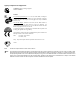
3.2 Loading Media Load media into the printer as follows: 1. Open the media cover and lower the Media Hub Guide and Media Guide. 2. Press in on the Printhead Latch and raise the Printhead Assembly.
3. Slide the Roll Media onto the Media Hub and raise the Media Hub Guide. The Media Hub Guide should be pushed inward so that it is just touching the Roll Media. 4. Route the Media through the printer as shown. Raise the Media Guide. The Media Guide should be pushed inward so that it is just touching the edge of the Media.
5. Close the Printhead Assembly and press down until it locks into place. 6. Close the cover and press the FEED button several times to position the media and ensure proper tracking. If the printer does not correctly sense the top of each label, as denoted by the perform the Calibration Procedure, see section 4.7.1. ERROR light, it may be necessary to ; Note: The printer is factory set to use 4-inch media (and ribbon, if thermal transfer equipped).
3.3 Media Sensor Adjustment The Media Sensor needs to be positioned so that the printer can detect the presence of media and the top-of-form (except for continuous stock, where the TOF is set through the front panel, (see ‘CONT FORM LENGTH’, Section 4.5.2). To adjust: n With media loaded, as described in Section 3.2, grasp the Slide Tab and move the Sensor Eye Mark into position over media according to the table below. o If loading media, return to the media loading instructions.
3.4 Loading Ribbon Ribbon is required with thermal transfer media. It is recommended that the width of the ribbon be slightly wider than the media being used. Depending upon the type of Ribbon Supply Hub (see 3.4.1 for examples), the printer must use either ribbons with the ‘coating side in’ or ribbons with the ‘coating side out’. To load: ; Note: Using a ribbon that is slightly wider than your media (and liner, if any) will help protect against printhead wear. 1. Open the media cover.
4. Close the Printhead Assembly and press down until it locks into place. 5. Route the ribbon up and then around to the Ribbon Take-Up Hub, winding it several times in a clockwise direction to secure it in place. 6. Close the cover and press the FEED button several times to position the ribbon and ensure proper tracking. 7. The ‘Media Type’ setting within the printer’s setup must be set to ‘Thermal Transfer’ to print using a ribbon, see section 4.5.2.
3.4.1 Ribbon Routing (Coated Side In & Coated Side Out) ; Note: Directional Arrows near the Ribbon Supply Hub indicate the correct ribbon route. Ribbon types are available with the ink (coating) layer wound ‘in’ or ‘out’. These types are NOT interchangeable for use with the printer. ; Note: Ensure the inked side of the ribbon faces the media and NOT the printhead.
4.0 Introduction The Front Panel consists of three indicator lights and three function buttons. The functions of these lights and controls are listed in the following sections. 4.1 Lights (Normal power-up) Normal Mode STOP ERROR READY ¾ Both the READY 16 and Solid On: Indicates the printer is in the ‘Paused’ state Flashing: (When using the Peel & Present Option) Indicates a label is presented to the operator.
4.2 Buttons PAUSE , CANCEL perform different functions based on the printer’s The three buttons, FEED , and operational mode. The printer operates in one of the following modes: Normal: Normal printer functions. See Section 4.3. Express Setup: Allows quick access to the most common printer settings, (Sensor Type, Media Type, and Option Control. See Section 4.4. Printer Setup: Allows changes to the printer’s operational settings. See Section 4.5. Calibration: 4.
4.4 Express Setup Mode - Button Functions The Express Setup is a unique printer feature that allows users quick access to the most commonly used printer settings. The selected setting is represent by a specific combination of the printer’s indicator lights for each of the three items, (Sensor Type, Media Type, and Option Control). To enter the Express Setup… Turn the printer OFF to save settings.
4.5 Printer Setup Mode - Button Functions In ‘Printer Setup’ mode, the buttons control the setting of the printer’s operational items such as media settings, communications, and options as detailed below. ; Notes: It is recommended that the Printer Setup Mode not be entered while in Peel Mode or with the optional Present Sensor enabled. Depending on label size this can cause unpredictable results. Printer and cutter faults are disabled during , but can still occur while printing “test” labels.
4.5.1 Printer Setup Menu List The Printer Setup Menu List label, shown below, contains the printer’s current values for each menu item that can be modified via the front panel (See Section 4.5.2 for a detailed item description.) FEED button The Menu Item Numbers correspond to the item’s position in the Menu List for selection when pressing the during the Printer Setup Procedure (see Section 4.5).
4.5.2 Menu Items and Values The table below details the Printer Setup Menu List items with a brief description of the item’s function, and the possible values. A “*” denotes the default setting. M-4206 1) MEDIA TYPE 2) SENSOR TYPE Sets printing for direct thermal (no ribbon) or thermal transfer (ribbon) media. Selects the sensor type used to detect the media’s Top Of Form (TOF) mark.
9) CONTROL CODES 10) CONT FORM LENGTH Allows code selection listed in Programmer’s manual. Sets the page (label) size when the ‘SENSOR TYPE’ is set to continuous media. Possible Values: * (STD) Standard Codes (ALT) Alternate Codes Possible Values: 11) OOS MAXVOLT 12) TOF GAIN Sets the media sensor level for the Out Of Stock condition. Sets media sensor Top of Form gain value. Possible Values: Possible Values: Range: 0 – 16; nominal = *2 (Units = .
19) ALIGN LENGTH 20) STOP LOCATION Leading edge distance of two successive labels. Must be entered if ‘LABEL ALIGNMENT’ is set to Yes (see Section 4.6). Sets label stopping (and in certain cases the starting) location for different printer configurations. Possible Values: 0 – 999; default =100* (Units = .01 inch) Possible Values: * AUTO (Automatically sets the stop location. Installed options will be ‘auto-sensed’ and the appropriate stop position will automatically be set. Host commands are ignored.
4.5.3 Step by Step Modification of the Printer Setup The following is an example of Printer Setup modification. Although this example will detail how to modify the serial Baud Rate, the same method can be used to change any of the printer’s menu item settings. ; Note: It is recommended that the Printer Setup Mode not be entered while in Peel Mode or with the optional Present Sensor enabled. Depending on label size this can cause unpredictable results. 1.
CANCEL buttons simultaneously, this will print the FEED + 6. To confirm that your changes have been made press the Database Configuration Label. The label should show the new Baud Rate value of 19200. FRI JANUARY 10, 2003 19:29 010 VER: M4206 - 05.
4.6 Label Alignment The Label Alignment function is intended for use when the label length is less than the distance between the printhead and the media sensor or where label waste at power-up is a concern. Label Alignment (see table below) is not recommended for label lengths greater than 6.5 inches or for media containing 2 or more form lengths. Label Stock Continuous 6.5 inches or less 6.
4.6.2 Label Alignment = AUTO In this mode, the printer automatically calculates the ‘ALIGN LENGTH’ thus eliminating the need to physically measure the label. This mode is usually preferred in applications that require frequent media changes to labels of different lengths. FEED button (about 4 seconds). The printer will To perform an Auto Alignment, in Normal Mode press and hold the feed labels to calculate the label length.
4.6.4 Label Alignment Troubleshooting If you experience label alignment problems, the following table offers possible causes and solutions. Problem Attempting to perform Label Alignment results in no paper movement. Possible Cause With the Present Sensor enabled, Label Alignment cannot be performed without a Label Length. Solution FEED until ¾ Set Label Alignment to AUTO, press and hold media moves for the automatic length measurement. ~OR~ ¾ Re-measure the Label Alignment Length.
Problem Label Alignment is incorrect. Pressing FEED successively results in a label length longer than actual, oneinch. Tear Mode is selected but the label stop position (present position) is not far enough forward. Possible Cause Label Alignment Length is not correct. The default Label Alignment Length is 1.00”, and will result in this behavior when any larger label length is used without setting the appropriate length Another present position has been determined.
4.7 Calibration Mode – Button Functions In ‘Calibration’ mode, the buttons allow the printer to adjust to the media being used. Calibration can be performed either automatically or manually, as detailed below. ; Notes: Before calibrating, ensure that the Printhead Carrier Assembly is latched down, that the cover is closed, and that the media sensor has been set for the appropriate media type, see Section 4.5.2. Printer and cutter faults are disabled during printing “test” labels.
4.7.1 Auto Media Sensor Calibration Auto Media Sensor Calibration automatically establishes the optimum sensing values for the media you are using in the printer. ; Note: Before calibrating, be sure the media sensor is set for the appropriate media type, see Section 4.5.2; also, ensure that the Printhead Carrier Assembly is latched down and the cover is closed. To automatically calibrate the media sensor: 1. With the desired media loaded, hold the CANCEL button while powering up the printer.
4.7.2 Manual Media Sensor Calibration The Manual Media Sensor Calibration procedure should be used in cases where the printer continues to suffer from media sensing problems after performing or attempting to perform the Auto Media Sensor Calibration (see Section 4.7.1). ; Note: Before calibrating, be sure the media sensor is set for the appropriate media type, see Section 4.5.2; also, ensure that the Printhead Carrier Assembly is latched down and the cover is closed.
4.8 Internal Labels The following section details the printer’s internally generated configuration and test labels. 4.8.1 Database Configuration and Dot Check Labels The Database Configuration Label provides valuable printer information including the firmware version, memory allocations, enabled options, and label-counter data.
The second label printed is the Dot Check Label. This label is used to test the condition of the printhead, as shown below: Good Dot Check Label: Even pattern consistency indicates that the printhead is operating normally. Faulty Dot Check Label: Streaks in the patterns indicate a dirty or faulty printhead (see Chapter 5).
4.8.2 Test Label The Test Label is used to evaluate the current printer setup for print quality, label tracking, and print positioning. To print the Test Label: With the printer loaded with media (at least 4 inches wide), and ribbon (if printing with thermal transfer media), FEED buttons.
4.8.3 Hex Dump Label The Hex Dump Label is a useful tool in the diagnosis of problems including communications handshaking and DPL syntax errors. To generate a Hex Dump Label the printer enters into Hex Dump Mode. In this mode, all data sent to the printer will be immediately output in hexadecimal code, along with the printable ASCII equivalents. To decode this information, the Programmer’s Manual is an essential reference.
5.0 Introduction This chapter details the cleaning, adjusting, and troubleshooting tips for the printer. The following table outlines the recommended maintenance schedule for the various printer parts. Area Printhead Media Path Method Turn off the printer before cleaning the printhead. Use solvent* on a cotton swab to clean the printhead from end to end. Turn the power off. Rotate the platen roller and clean it thoroughly with solvent* and a cotton swab.
5.1 Cleaning the Printhead If print quality declines (symptoms include non-compliant bar codes, print dropouts, streaks), the typical cause is debris build-up on the printhead. Furthermore, when the build-up is not removed it may lead to element failure, greatly reducing the life of the printhead. To clean the printhead: 1. Turn ‘Off’ and unplug the printer. 2. Open the cover. Unlock the Printhead Latch and raise the Printhead Assembly. Allow the printhead to cool before proceeding. 3.
5.2 Media Width Adjustment When printing on less than full width media, the printer has a printhead-leveling cam to adjust the right side of the printhead for even pressure distribution. To adjust the leveling cam: 1. With media loaded in the printer, print a label (press the CANCEL buttons simultaneously) and FEED + examine it.. 2. While observing the printed labels, loosen the Thumbscrew and move it to the left most position. (see Example 1, below). 3.
5.3 Printhead Burn Line Adjustment The Burn Line has been adjusted at the factory for strict compliance using 6.5-mil (.0065 inch) media, ensuring print quality across a majority of media types. In extreme cases, however, if media of a different thickness or rigidity is used (for example, heavy tag stock), print quality can change. Typically, thicker media requires a slight forward adjustment, while thinner media requires a slight backward adjustment.
5.4 Printhead Pressure Adjustment To accommodate a variety of media types, the pressure applied by the printhead assembly is adjustable. This pressure is factory set to work with most media types, so this adjustment should only be performed after attempting to improve print quality through the use of the (1) heat and/or (2) print speed. When adjusting, use only the minimum pressure necessary for better imaging. To adjust: 1. Load at least 4” (102mm) wide media and ribbon, see Section 3.2. 2.
5.5 Printhead Replacement Removal: ; Note: Printheads are fragile; use extreme care when handling and never use a sharp object on the surface. If you have questions, contact a qualified technician or Datamax Technical Support before proceeding. 1. Touch a bare metal part of the printer’s frame to discharge any static electricity that may be present on your body. 2. Turn ‘Off’ and unplug the printer. Open the cover; if ribbon is installed, remove it. 3.
5.6 Darkness Adjustment The Darkness Adjustment allows the operator to match the print contrast following a printhead replacement. Turning the Darkness Adjustment clockwise will darken the print, while turning it counterclockwise will lighten the print. Compare a label printed with the old printhead and make this adjustment so that the new printhead matches the darkest portion of that label. ; Note: Large increases in the ‘Darkness Adjustment’ can shorten printhead life.
5.8 Downloading Firmware and Fonts The operating programs and fonts for the printer are stored in Flash memory on the Main PCB. When program updates and/or new features are added, they can be downloaded to the printer as follows: 1. Identify the new version for your model of printer from the Datamax Web site at www.datamaxcorp.com and download it onto your computer’s hard drive or a floppy disk. 2. Ensure that the printer is connected to the host, (via parallel port only) and that the power is ‘On.
6.0 Introduction Occasionally, situations arise that require troubleshooting. Possible problem situations and potential solutions are listed in this section. While not every situation is addressed, you may find some of these tips helpful. After the correction action is FEED button to clear the alarm. Contact a qualified service technician for problems that persist or are taken press the not covered in this section. 6.
Unacceptable print quality Dirty printhead: Clean the printhead (see Chapter 5). The temperature setting may be incorrect for the media being used: Use the software program or DPL commands adjust the Heat Setting and Print Speed. A mismatched incorrect ribbon/media combination is being used: Check the types being used. Verify that the Media Type is set correctly for the printing method being used (see Chapter 4). Faulty printhead: Replace it (see Chapter 5) or call for service.
Skips every other label (Print quality is good, but every other label is skipped). The label is formatted too close to the top edge of the label: Leave white space equal to 8-dot rows (about .02 inch [.5mm]) at the top of the label. The media is not calibrated: Calibrate it (see Chapter 4). The Media Sensor may need to be repositioned (see Chapter 3). The media sensor or media sensor circuitry may be defective: Call for service.
Label advances 16 inches before a fault indication The media may not be properly loaded: Reload it (see Chapter 3). When loading media ensure that the media hub and media guide are against the media and that gaps or marks in the labels are in line with the media sensor. The Media Sensor may need to be repositioned (see Chapter 3). The media sensor or media sensor circuitry may be defective: Call for service.
Mechanical Width 9.8” (24.9 cm) Depth 18.06” (45.9 cm) Height 10.3” (26.2 cm) Weight 21.5 lbs. (9.77 kg) Operating Temperature 40 F to 95 F (4 C to 35 C) Humidity 10% AC Input Voltage 90 – 132 or 180 – 264 VAC @ 47–63 Hz, auto-ranging.
Media/Ribbon Media Types Roll-Fed, Die-Cut, Continuous, Fan-Fold Max. Media Width 4.65" (118 mm) Min. Media Width 1" (25.4 mm) Max. Print Width 4.09" (104 mm) Print Length Range .25 - 99" (6 - 2475 mm) Media Thickness Range .0025 - .01" (.064 mm - .254 mm) Media Supply Roll Capacity Ribbon Width Range 8" (203 mm) O.D. on 1.5 - 3.0" (38 – 76.2 mm) cores 1.0 - 4.5" (25 - 114 mm) Ribbon Roll Capacity Matched to media: approx. 1476’ (450 m) long Ribbon Core: 1.010” .006” (25.6 mm .
Approved Media To achieve optimum print quality and maximum printhead life, Datamax specifies the use of DATAMAX brand media and ribbons. These supplies are specially formulated for use in our printers; use of non-Datamax supplies may affect the print quality, performance, and life of the printer or its components. For a current list of approved media and ribbons for use in direct thermal and thermal transfer applications, please contact a Media Representative at (407) 523-5650.
52 M-4206
ASCII Control Code Chart Ctrl @ Ctrl A Ctrl B Ctrl C Ctrl D Ctrl E Ctrl F Ctrl G Ctrl H Ctrl I Ctrl J Ctrl K Ctrl L Ctrl M Ctrl N Ctrl O Ctrl P Ctrl Q Ctrl R Ctrl S Ctrl T Ctrl U Ctrl V Ctrl W Ctrl X Ctrl Y Ctrl Z Ctrl [ Ctrl \ Ctrl ] Ctrl ^ Ctrl _ M-4206 Char Dec Hex NUL SOH STX EXT EOT ENQ ACK BEL BS HT LF VT FF CR SO SI DLE DC1 DC2 DC3 DC4 NAK SYN ETB CAN EM SUB Esc FS GS RS US 0 1 2 3 4 5 6 7 8 9 10 11 12 13 14 15 16 17 18 19 20 21 22 23 24 25 26 27 28 29 30 31 00 01 02 03 04 05 06 07 08 09 0A 0B
Cha r Ç ü é â ä à å ç ê è è ï î ì Ä Å É Æ Æ ô ö ò û ù ÿ Ö Ü Ø £ Ø x ƒ Dec Hex Char Dec Hex 128 129 130 131 132 133 134 135 136 137 138 139 140 141 142 143 144 145 146 147 148 149 150 151 152 153 154 155 156 157 158 159 80 81 82 83 84 85 86 87 88 89 8A 8B 8C 8D 8E 8F 90 91 92 93 94 95 96 97 98 99 9A 9B 9C 9D 9E 9F á í ó ú ñ Ñ a 160 161 162 163 164 165 166 167 168 169 170 171 172 173 174 175 176 177 178 179 180 181 182 183 184 185 186 187 188 189 190 191 A0 A1 A2 A3 A4 A5 A6 A7 A8 A9 AA AB AC AD AE
Embedded Fonts and Barcodes All character fonts and barcodes available with the printer are described in this section. Each font and barcode has a name associated with it for use in programming. Human-readable fonts have numeric names while barcode fonts have alpha names. Fonts Fonts 0 through 8 use the slash zero (Ø) conventions for distinguishing between the zero and the alphabetic O. The slash can be removed with the label formatting command Z.
The table below lists the font sizes. The numbers indicate the number of dots. FONT Font 0 Font 1 Font 2 Font 3 Font 4 Font 5 Font 6 Font 7 Font 8 HEIGHT 7 13 18 27 36 52 64 32 28 WIDTH 5 7 10 14 18 18 32 15 15 SPACING 1 2 2 2 3 3 4 5 5 Font 0 96-character alphanumeric, upper and lower case. Font 1 145-character upper and lower case alphanumeric w/ descenders and ascenders. Font 2 138-character alphanumeric, upper and lower case. Font 3 62-character alphanumeric, uppercase.
Font 4 62-character alphanumeric, uppercase. Font 5 62-character alphanumeric, uppercase. Font 6 62-character alphanumeric, uppercase.
Font 7 OCR-A, size I. Font 8 OCR-B, size III. Font 9 Internal Triumvirate font. Point sizes are selected by the number in the barcode height. Larger point sizes can be obtained by increasing the height and width multipliers, 48pt and 72pt fonts are generated by doubling the 24pt and 36pt fonts respectively (see the Programmer's Manual for more information).
Barcodes Bar Code fonts have alpha names (left column in the table below). Uppercase alpha names will print barcodes with human-readable interpretations. Lowercase alpha names will print barcodes only. The table is followed by visual samples.
Bar Code ID Type Length Checksum u UPS MaxiCode with Byte Count FIM PDF417 PDF417 with Byte Count DataMatrix DataMatrix with Byte Count QR Code – Auto format QR Code – Manual format Aztec Aztec with Byte Count TCIF Linked Barcode 3 of 9 (TLC39) MicroPDF417 MicroPDF417 with Byte Count Specified Yes Valid ASCII Characters, decimal value representation Alphanumeric 1 Varies Specified No Yes Yes A, B, C, D All All Varies Specified Yes Yes All 8-bit values All 8-bit values Varies Yes Alphanumeri
Barcode A Code 3 of 9 Barcode B UPC-A Barcode C UPC-E Barcode D Interleaved 2 of 5 Barcode E Code 128 Barcode F EAN-13 Barcode G EAN-8 Barcode H Health Industry Barcode (HIBC) M-4206 61
Barcode I Codabar Barcode J Interleaved 2 of 5 w/module 10 checksum Barcode K Plessey Barcode L Interleaved 2 of 5 w/module 10 checksum and shipping bearer bars Barcode M 2 Digit UPC addendum Barcode N 5 Digit UPC addendum Barcode O Code 93 Barcode p Postnet 62 M-4206
Barcode Q UCC/EAN Code 128 Barcode R UCC/EAN Code 128 KMART NON EDI Barcode S UCC/EAN Code 128 Random Weight Barcode T Telepen M-4206 Barcode u UPS MaxiCode 63
Barcode v FIM Barcode z PDF417 Bar Code W1c: DataMatrix Bar Code W1d: QR Code Bar Code W1f: Aztec Bar Code W1z: MicroPDF417 Bar Code W1T: TCIF Linked Barcode 3 of 9 (TLC39) 64 M-4206
Datamax Barcode Products Limited Warranty Statement M-Class™ Printer Printer Datamax warrants to Purchaser that under normal use and service, the M-Class™ Printer, (with the exception of the thermal printhead) purchased hereunder shall be free from defects in material and workmanship for a period of (365) days from the date of shipment by Datamax. Expendable and/or consumable items or parts such as lamps, fuses, labels and ribbons are not covered under this warranty.
Warranty Service Procedures If a defect should occur during the warranty period, the defective unit shall be returned, freight and insurance prepaid, in the original shipping containers, to Datamax at: 4501 Parkway Commerce Blvd., Orlando, Florida, 32808. A Return Material Authorization (RMA) number must be issued before the product can be returned. To open an RMA please call the Datamax Customer Service Department at (407) 523-5550.
Glossary alphanumeric Consisting of alphabetic, numeric, punctuation and other symbols. backing material The silicon-coated paper carrier material to which labels with adhesive backing are affixed. Also referred to as “liner”. bar code A representation of alphanumeric information in a pattern of machine-readable marks. The basic categories are divided into one-dimensional (UPC, Code 39, Postnet, etc.) and two-dimensional barcodes (DataMatrix, MaxiCode, PDF417, etc.).
direct thermal media Media coated with special chemicals that react and darken with the application of heat. DPI (dots per inch) A measurement of print resolution, rated in the number of thermal elements contained in one inch of the printhead. Also referred to as “resolution”. DPL (Datamax Programming Language) programming commands used specifically for control of and label production in Datamax printers. A complete listing of commands can be found in the Programmer’s Manual.
notched stock Media, typically tag stock, with holes or notches in the material that is used to signal the top of form. The printer must be set to ‘gap’ to use this media type. preprinted media Label stock that contains borders, text, or graphics, floodcoating, etc. perforation Small cuts extending through the backing and/or label material to facilitate their separation. Also referred to as “perf”. print speed The speed at which the media moves under the printhead during the printing process.
70 M-4206