ST/SV 3210 & ST/SV 3306 Operator’s Manual
CG Triumvirate is a trademark of Agfa Corporation. Copyright Information: Firmware (Software) Agreement The enclosed Firmware (Software) resident in the EPROM’s is owned by Licensor or its suppliers and is licensed for used only on a single printer in the user’s Trade or Business. The User agrees not to, and not to authorize or permit any other person or party to, duplicate or copy the EPROM’s or the information contained in the EPROM’s.
Agency Compliance and Approvals: UL1950 Information Technology Equipment C22.2 No. 950-M93 C US Listed EN60950 For 230 Volt Operation (Europe): Use a cord set, marked "HAR," consisting of a min H05VV-F cord which has a minimum 0.
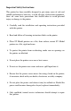
Important Safety Instructions: This printer has been carefully designed to give many years of safe and reliable performance; however, as with all types of electronic equipment, there are some basic precautions that should taken to avoid personal injury or damage to the printer: Ø Carefully read the installation and operating instructions provided with this printer. Ø Read and follow all warning instruction labels on the printer.
Contents Printer Overview 1.0 About the Printer ...........................................................1 1.0.1 Standard Features...........................................2 1.0.2 Optional Features............................................3 Getting Started 2.0 Unpacking the Printer ...................................................5 2.0.1 Inspection ........................................................6 2.0.2 Additional Requirements .................................6 Setting up the Printer 3.
4.1 4.2 4.3 4.4 4.0.2 SV Model .......................................................23 Stock ID Selections.....................................................24 Start of Print & Cut/Tear Adjustment...........................26 Operational Database Modification.............................27 4.3.1 Database Modification Example ....................30 Maintenance ...............................................................31 4.4.1 Cleaning the Printhead ..................................32 4.4.
Warranty Information ..................................................65 Glossary ..........................................................................69 Index .................................................................................
iv
Printer Overview 1.0 About the Printer ST (Table) Model SV (Vertical) Model The ST-3210, SV-3210, ST-3306 and SV-3306 printers, hereafter referred to as ‘the printer’, blend rugged design with state-of-the-art electronics and user-friendly features to redefine industry printer standards. This printer is equipped with a 32-bit microprocessor and four megabytes of standard memory to process complicated formats quickly and easily.
1.0.1 Standard Features This printer offers these standard features. Printing: Ø Ø Ø Ø Direct Thermal printing On-Demand and Batch printing modes Automatic ticket loading and top of form positioning 3.375” x 11.375” Interior Fan-Fold Ticket Stock Platform (ST Models only) Ø Integral Tearbar Ø Lockable Side Cover (ST Models only) Ø DPL and DTPL programming language support Memory: Ø 1 MB EPROM Program Memory Ø 4 MB DRAM Memory Communication Interfaces: Ø One RS-232 or RS-422 serial interface port.
1.0.2 Optional Features This printer offers these optional features. Cutter and Tray (ST Models only): Ø A factory-installed device that will cut stock with a maximum thickness of .008 inch (.2 mm) and a minimum thickness of .0025 inch (.06 mm). The tray attaches to the front of the printer to collect cut tickets, and is capable of stacking a minimum of 100, 3.5-inch (88.9 mm) wide tickets, ranging in lengths from 2.0 inches (50.8 mm) to 5.63 inches (142.9 mm).
4 ST/SV-3210 and ST/SV-3306
Getting Started 2.0 Unpacking the Printer Inspect the shipping container(s) for damage; if evident, notify the shipping carrier to report the nature and extent of the damage before proceeding. The printer is carefully packaged to avoid any damage during transit. In order to operate the printer, you will need to remove the packaging materials placed there for shipment. Complete the following steps prior to connecting power or attempting to load ticket stock.
2.0.1 Inspection After removing and inspecting the printer, check the remaining contents of the container. In addition to this manual, the following items should be included: Ø Ø Ø Ø Ø Ticket Printer Power cord Keys (ST Models only) Accessories CD Special or additionally purchased items. 2.0.2 Additional Requirements The following items are necessary for generating printed tickets using the printer.
Setting up the Printer This section details the connections, loading methods, memory module installation, and resident ticket formats of the printer. 3.0 AC Voltage Configuration Depending upon the configuration of the AC Selection Switch and fuse, the printer is capable of either 115 or 230 VAC single-phase operation.
3.1 Interfacing the Printer Interfacing the printer to the host computer can be made through either a parallel or a serial cable (see Appendix C for cable requirements). Communication port selection is automatic: the first port to receive data is set ‘active’ by the printer. To change an active port, cycle the power ‘Off’ and ‘On’ or perform a Warm Reset (see Section 3.6.1). Parallel Interface Port: The parallel interface supports Centronics parallel communications.
Printer power and interface connections: Follow these instructions to connect the printer. Œ Turn ‘Off’ the power to the Host Computer. • Verify that the Printer’s AC Configuration has been set; see Section 3.0. Ž Connect the interface cable securely between the Printer and Host communication ports. • Verify that the Power Switch is in the ‘Off’ position and connect the AC Power Cord to the AC Power Connector, then to the AC Outlet. • Turn ‘On’ the Printer and then the Host Computer.
3.2 Loading Ticket Stock Both printers feature an automatic ticket loading and positioning mechanism, although the initial loading instructions differ slightly according to model and options. 3.2.1 ST Models Œ Plug in and turn ‘On’ the printer. • Insert the Key and unlock the Access Cover. Ž Raise the Access Cover (for convenience the cover may be removed by sliding it forward and then up). • Place fanfold ticket stock (with the TOF Mark facing down; see Section 4.
To use roll ticket stock, the stock must be mounted on the optional Roll Hanger, as shown. (See Section 6 for stock requirements.) þ Note: To use an internal fanfold ticket source on a printer equipped with the Roll Hanger option, first remove the Roll Hanger by unscrewing it from the printer. Store the hanger in a safe place for future use.
3.2.2 SV Models Œ Plug in and turn ‘On’ the printer. • Place fanfold ticket stock in the bottom of the enclosure, bring the stock up to the Media Guides. (The TOF Mark should be facing away from the Printhead Latch; see Section 4.) Ensure that the Printhead Latch is locked. Ž Loosen the Thumbscrew and adjust the Media Guides to fit the width of the ticket stock as described in Step 5 of Section 3.2.1. • Slide the ticket stock through the Media Guides. The motor will start; continue feeding the tickets.
3.3 Installing a Memory Module Optional Flash Memory Modules offer convenient, non-volatile storage of formats, fonts and graphics. Refer to the DPL Programmer’s Manual (part number 88-2051-01) for programming and use details. To install a module: Œ Turn ‘Off’ the printer. • Place the Memory Module’s ‘write protect’ switch into the desired position (in the ‘On’ position the module cannot be written to). Ž Carefully insert the Memory Module into the Memory Module Slot. • Turn the printer ‘On’.
3.4 Using the Front Panel The Front Panel on both models is comprised of a ticket exit, darkness control, three indicator lights, and three dual-purpose buttons.
Ticket Exit The printed tickets are expelled from this opening. Darkness Control The Darkness Control will adjust the darkness of the printing on the tickets: turning the control clockwise darkens the print and turning the control counterclockwise lightens the print. This darkness function can also be controlled through software commands. Indicators For a brief period (approximately 20 seconds) after power-up, all three indicators will remain on while the printer performs internal diagnostics.
Power-Up and Off-Line Mode Button Functions (the On-Line Indicator is ‘Off’) Ø F2: Three functions: (a) Press momentarily to advance ticket stock, or to manually load ticket stock. (b) Press and hold during power-up to print a Configuration and Test Pattern Ticket, and enter Character Dump mode. (c) Press and hold to enter the Operational Database Modification mode; see Section 4.3 for details. Ø F3: Two functions: (a) Press and hold to enter the Start of Print and Cut/Tear Adjustments; see Section 4.
3.5 Resident Formats Stored within the memory are several ticket formats that provide useful setup, operational, and problem diagnosis information. Load stock that is at least 2 inches (51 mm) wide to capture all the data on these resident formats. 3.5.1 Configuration Ticket The Configuration Ticket provides memory, firmware, and installed options information (depending upon the printer model, options, and age this information will vary).
3.5.2 Test Pattern Ticket The Test Pattern Ticket is a resident format that can be used to determine general print quality and the condition of the printhead. Œ With stock loaded, turn the printer ‘On’. • Press the PAUSE button to put the printer in the off-line mode. Ž Simultaneously press the F1 and F2 buttons. A “Good” Test Pattern Ticket: Consistent print patterns across the width of the ticket indicate that the printhead is operating normally.
3.5.3 Internal Test Ticket The Internal Test Ticket is another resident format that is another useful indicator of print quality. This ticket features various font sizes and barcodes (the sample below was printed using the ST-3210). To print an Internal Test Ticket: Œ With stock loaded, turn the printer ‘On’. • Press the PAUSE button to enter the off-line mode. Ž Press the F3 button.
3.6 Resetting the Printer There are two different reset levels possible for the printer: 3.6.1 Warm Reset To reset the printer and return to the on-line mode: Press the PAUSE button to go off-line and then press the F1 + F3 buttons simultaneously. 3.6.2 Factory Default Reset To return the printer to default database settings (see the table below), perform the following procedure. Œ Turn the printer ‘Off’. • Press and hold the PAUSE/F1, FEED/F2 and TEST/F3 buttons while turning ‘On’ the printer.
Adjusting and Maintaining the Printer This section details important adjustments, settings and periodic maintenance requirements that will ensure optimum printer performance. 4.0 TOF Sensor Adjustment The TOF Sensor in the printer has two functions: (1) sensing the presence of ticket stock and (2) when using reflective stock, sensing the Top of Form (TOF) Mark on each ticket. If the ticket stock does not contain TOF Marks, DPL programming must be used to set the ticket size.
4.0.1 ST Model TOF Sensor Adjustment Œ Insert the Key and unlock the Access Cover. • Raise the Access Cover. (For convenience, the cover may also be removed by sliding it forward and then off.) Ž Unlock the Printhead Latch and raise the Printhead Assembly. • Grasp the Slide and move it ‘in’ or ‘out’ accordingly, so the position of TOF Sensor is underneath the TOF Mark and within a quiet zone area of the ticket stock. • Lower the Printhead Assembly and lock the Printhead Latch.
4.0.2 SV Model TOF Sensor Adjustment Œ Unlock and raise the Printhead Assembly. • Grasp the TOF Sensor and move it ‘in’ or ‘out’ accordingly, to position the sensor underneath the TOF Mark and within a quiet zone area of the ticket stock. Ž Lower the Printhead Assembly and lock the Printhead Latch. • Re-feed the ticket stock; see Section 3.2.
4.1 Stock ID Selections The printer maintains a selection of 10 user modifiable stock setups. Each setup defaults to a specific print width, start print position and cut/tear position, where: Ø The Print Width is the print distance across the ticket. Ø The Start of Print Position is the distance, measured in inches, from the TOF Sensor to printhead burnline. Ø The Cut/Tear Position is the distance, measured in inches, from the TOF Sensor to the cut (if equipped) or tear position of the printed ticket.
The table below lists the default settings, according to the printer model, for each Stock ID number. Stock ID Default Settings Stock ID 0 1 2 3 4 5 6 7 8 9 Print Width 3210 Models 3306 Models 3.15" (80.0 mm) 3.20" (81.3 mm) 3.15" (80.0 mm) 3.20" (81.3 mm) 3.15" (80.0 mm) 3.20" (81.3 mm) 3.15" (80.0 mm) 3.20" (81.3 mm) 1.89" (48.0 mm) 1.81" (46.0 mm) 1.89" (48.0 mm) 1.92" (48.8 mm) 1.89" (48.0 mm) 1.92" (48.8 mm) 1.89" (48.0 mm) 1.92" (48.8 mm) 2.20" (55.9 mm) 2.24" (56.9 mm) 3.15" (80.0 mm) 3.20" (81.
4.2 Start of Print & Cut/Tear Adjustment If none of the preset Stock ID parameters meet the needs of your application, then the Start of Print (SOP) and Cut/Tear (C/T) Adjustments can be used to visually set the required positions. To begin: Œ If on-line, press the PAUSE button to place the printer off-line. • Press and hold (approximately 6 seconds) the F3 button until the OnLine Indicator is lit then release.
4.3 Operational Database Modification The operational database for the printer, which contains the parser mode setting and other important printer parameters, can be changed using the front panel. To change the Operational Database settings: Œ If on-line, press the PAUSE button to place the printer off-line. • Press and hold the F2 button until the On-Line Indicator is lit (approximately six seconds) then release.
Operational Database: ST/SV-3210 Models Parameter Stock ID Label (Ticket) Width Description Stock ID number Width of the ticket stock used for printing. Parser Mode Print Speed* Slew Speed* Backup Speed* Baud Rate Sets the emulation of the printer Speed during printing Speed during feeding Speed during backup Serial communication speed Word Length Communicated word length Cutter Equip Presence of the optional cutter will be sensed automatically.
Operational Database: ST/SV-3306 Models Parameter Stock ID Label Width Description Stock ID number Width of the ticket stock used for printing. Parser Mode Print Speed* Slew Speed* Backup Speed* Baud Rate Sets the emulation of the printer Speed during printing Speed during feeding Speed during backup Serial communication speed Word Length Communicated word length Settings 0-9 (see Section 4.1) 1.81 inches (46.0 mm) 1.92 inches (48.8 mm) 2.03 inches (51.6 mm) 2.14 inches (54.4 mm) 2.24 inches (56.
4.3.1 Database Modification Example This section details the modification of an Operational Database parameter. The following example increases the printing speed parameter from 6 to 8 IPS on the ST-3210; however, using the same basic procedure, any of the parameters can be changed regardless of the printer model. Œ If on-line, press the PAUSE button to place the printer off-line. • Press and hold the F2 button until the On-Line Indicator is lit (approximately six seconds) then release.
4.4 Maintenance Routine maintenance will ensure the optimum performance of the printer. The following table outlines the recommended cleaning intervals, while the items listed below will help do the job safely and effectively: • Isopropyl alcohol • Cotton swabs • A clean, lint-free cloth • Soft-bristle brush • Soapy water/mild detergent • Compressed air For your continued safety and to avoid damage to the unit, always turn ‘Off’ and unplug the printer before servicing.
4.4.1 Cleaning the Printhead Declining print quality (i.e., dropouts, streaking, or smudging) is usually caused by a surface build-up of dirt on the printhead; see Section 3.5.2 for an example. Left unattended, this build-up can lead to permanent printhead damage. To clean: Œ Turn ‘Off’ and unplug the printer. • ST Models: Raise the access cover; see Section 3.2. Ž Slide the Printhead Latch to the Unlocked position then raise the Printhead Assembly.
4.4.2 Cleaning the Platen Roller Print quality can decline if the platen roller becomes contaminated with paper dust, grit or adhesive. When this build-up is not removed, it can cause abrasive damage to the printhead. To clean the Platen Roller: Œ Turn ‘Off’ and unplug the printer. • ST Models: Raise the access cover; see Section 3.2. Ž Slide the printhead latch to the unlocked position, raise the Printhead Assembly (see Section 4.4.1) and remove the ticket stock.
4.4.3 TOF Sensor Cleaning If the TOF Sensor becomes blocked with paper particles, Top of Form detection can be inconsistent or fail completely. To clean the sensor: Œ Turn ‘Off’ and unplug the printer. • ST Models: Raise the access cover; see Section 3.2. Ž Slide the printhead latch to the unlocked position, raise the Printhead Assembly (see Section 4.4.1) and remove the ticket stock. • Using a soft brush or compressed air, remove any debris accumulated on the TOF Sensor.
4.4.4 Ticket Detect Sensor Cleaning The Ticket Detect Sensor initiates the auto-loading process by signaling the presence of ticket stock within the Media Guides. If the sensor becomes blocked with paper particles, ticket feeding problems can occur. To clean the sensor: Œ Turn ‘Off’ and unplug the printer. • ST Models: Raise the access cover; see Section 3.2. Ž Slide the printhead latch to the unlocked position, raise the printhead assembly (see Section 4.4.1) and remove the ticket stock.
4.4.5 Interior Cleaning ST Models only: Ticket Compartment Cleaning During normal operation, paper particles from the ticket stock accumulate inside the printer. These particles can stick to the ticket and cause voids in the print, reducing print quality. To clean the interior of the printer: Œ Turn ‘Off’ and unplug the printer. • Raise the access cover; see Section 3.2. Ž Slide the printhead latch to the unlocked position, raise the Printhead Assembly (see Section 4.4.1) and remove the ticket stock.
Troubleshooting 5.0 Troubleshooting Tips This section addresses common problems and suggests solutions. While not all situations can be addressed, many suggestions may prove helpful; however, if a problem persists or is not covered in this text, contact Datamax Technical Support or a qualified service technician. þ Note: If the Fault Indicator is lit, the FEED button must be pressed to clear the alarm after completing the corrective action.
If experiencing this problem… No Communications: Try this solution… Ÿ The parser mode setting between the printer and host may not match; reconfigure, see Section 4.3. Ÿ The communication parameters between the printer and host may not match; reconfigure to match, see Section 4.3. Ÿ The interface connection may be faulty or the cable may be incorrect or faulty; check the connections and see Appendix C for cable requirements.
If experiencing this problem… Try this solution… After printing the ticket, the Fault Indicator lights: Ÿ If cutter equipped, this may indicate a cutter fault; call for service. Ÿ If not cutter equipped: a) Possible programming problem. b) Possible mechanical problem – try pressing the FEED button to clear the fault: if no response, call for service. Otherwise, the positioning of the TOF Sensor may need an adjustment (see Section 4.0).
If experiencing this problem… Try this solution… The printer does not print formats sent from the host, but the Fault Indicator remains off: • The parser mode setting between the printer and host may not match; reconfigure, see Section 4.3.1. • The communication parameters between the printer and host may not match; reconfigure, see Section 4.3.1. • The interface connection may be faulty or the cable may be incorrect or faulty; check the connections and see Appendix C for cable requirements.
5.1 Hex Dump Mode The hex dump mode is a useful tool for diagnosing problems, including communication and programming syntax errors. This mode allows a comparison of input strings to output data. Repeatedly sending a format can uncover handshaking problems (identified by sections of missing data in the output string). To decode this hexadecimal code and its printable ASCII equivalents, the DPL Programmer’s Manual or the DTPL Programmer’s Manual is an essential reference.
42 ST/SV-3210 and ST/SV-3306
Specifications 6.0 Specifications Communications Character Set: ANSI ASCII Parallel Interface Port: Centronics type 36-pin Serial Interface Port: RS-232c and RS-422; DB25 Baud Rates: 600, 1200, 2400, 4800, 9600, 19.2K and 38.4K Word Length and Parity: Selectable data format: 7-bit word with even parity, or 8-bit word with no parity Handshaking: Xon/Xoff and CTS & DTR. Input Buffer: Serial: Approximately 6 Kbytes. XOFF is transmitted and DTR goes low with 750 bytes available in the buffer.
Environmental Operating Temperature: 40°F to 100°F (4°C to 38°C) Storage Temperature: 32°F to 120°F (0°C to 49°C) Humidity: 10% to 95% non-condensing Ventilation: Free air movement Dust: Non-conducting, non-corrosive Electromagnetic Radiation: Moderate RF fields can be tolerated Fonts/Barcodes (See Appendix B for examples) Resident Fonts (parser mode setting dependent): DPL mode: Nine alphanumeric fonts from 0.035"H (0.89mm) to 0.
Mechanical Width: ST/SV-3210 ST/SV-3306 8.14 inches (20.7 cm) 8.05 inches (20.4 cm) Depth: ST/SV-3210 ST/SV-3306 14 inches (35.6 cm) 7.65 inches (19.4 cm) Height: ST/SV-3210 ST/SV-3306 10.5 inches (26.7 cm) 10.5 inches (26.7 cm) Weight: ST Models SV Models 22 pounds (10 kg) 18.8 pounds (8.46 kg) Top Plate: SV Models only 9.71 inches (24.7 cm) W X 8.60 inches (21.8 cm) DP X .09 inch (2.
Print Engine (continued) Maximum Fields and Characters Per Ticket: 600 fields with 16,000 characters per ticket Tear Bar: Tear up/down DRAM Memory: Internal Module Size: Scalable Module Size: 4 MB 512 KB (default) 256 KB (default) EPROM Memory: 1 MB Ticket Stock Requirements Type: Fan-fold and roll (if option reflective[1] direct thermal stock. equipped) Maximum Ticket Width: 3.25 inches (82.55 mm) Minimum Ticket Width: 1.9 inches (48.
6.1 Approved Ticket Stocks For optimum print quality and maximum printhead life, Datamax recommends using a ticket stock from the following table. Contact a Datamax Media Representative at (407) 523-5650 with any questions regarding your specific application. Manufacturer Ricoh Ricoh Kanzaki Material Comment Best quality for high-speed printing, 150 TLA 190 10 inches per second (IPS), and high quality applications. Recommended for use with the ST/SV-3306. Mid range.
48 ST/SV-3210 and ST/SV-3306
Appendix A ASCII Control Code Chart Ctrl @ Ctrl A Ctrl B Ctrl C Ctrl D Ctrl E Ctrl F Ctrl G Ctrl H Ctrl I Ctrl J Ctrl K Ctrl L Ctrl M Ctrl N Ctrl O Ctrl P Ctrl Q Ctrl R Ctrl S Ctrl T Ctrl U Ctrl V Ctrl W Ctrl X Ctrl Y Ctrl Z Ctrl [ Ctrl \ Ctrl ] Ctrl ^ Ctrl _ Char Dec Hex NUL SOH STX EXT EOT ENQ ACK BEL BS HT LF VT FF CR SO SI DLE DC1 DC2 DC3 DC4 NAK SYN ETB CAN EM SUB Esc FS GS RS US 0 1 2 3 4 5 6 7 8 9 10 11 12 13 14 15 16 17 18 19 20 21 22 23 24 25 26 27 28 29 30 31 00 01 02 03 04 05 06 07 08 09 0A
ASCII Control Code Chart Char Dec Hex Char Dec Hex Ç ü é â ä à å ç ê è è ï î ì Ä Å É Æ Æ ô ö ò û ù ÿ Ö Ü Ø £ Ø x ƒ 128 129 130 131 132 133 134 135 136 137 138 139 140 141 142 143 144 145 146 147 148 149 150 151 152 153 154 155 156 157 158 159 80 81 82 83 84 85 86 87 88 89 8A 8B 8C 8D 8E 8F 90 91 92 93 94 95 96 97 98 99 9A 9B 9C 9D 9E 9F á í ó ú ñ Ñ a ° ¿ ® 160 161 162 163 164 165 166 167 168 169 170 171 172 173 174 175 176 177 178 179 180 181 182 183 184 185 186 187 188 189 190 191 A0 A1 A2 A3 A4
Appendix B Available Fonts and Barcodes All available character fonts and barcodes are listed below. The selections will differ depending upon the parser mode setting. Accordingly, use either the DPL Programmer’s Manual or the DTPL Programmer’s Manual for detailed information. DPL Fonts Fonts 0 through 8 use the slash zero (Ø) convention for distinguishing between the zero and the alphabetic O (the slash can be removed with the Z ticket-formatting command).
The table below lists font sizes 0 – 8; the numbers indicate the number of dots. Font Number Font 0 Font 1 Font 2 Font 3 Font 4 Font 5 Font 6 Font 7 Font 8 Height 7 13 18 27 36 52 64 32 28 Width 5 7 10 14 18 18 32 15 15 Spacing 1 2 2 2 3 3 4 5 5 DPL Font Samples Font 0: 96 characters, alphanumeric, upper and lower case. Font 1: 145 characters, upper and lower case alphanumeric with descenders and ascenders. Font 2: 138 characters, alphanumeric, upper and lower case.
Font 4: 62 characters, alphanumeric, uppercase. Font 5: 62 characters, alphanumeric, uppercase. Font 6: 62 characters, alphanumeric, uppercase. Font 7: OCR-A, size I. ST/SV-3210 and ST/SV-3306 Font 8: OCR-B, size III.
Font 9: Internal CG Triumvirate font. The point sizes are selected by the number in the bar code height. Larger point sizes can be obtained by increasing the height and width multipliers. þ Note: Point sizes 4 and 5 are only available on the ST/SV-3306.
DTPL Font Samples All fonts contain ASCII characters (32-127); they are listed below by Font ID.
DPL Barcodes Uppercase alpha names will print barcodes with human readable interpretations; lowercase alpha names will print barcodes only.
DPL Bar Code Samples Bar Code A: Code 3 of 9 Bar Code B: UPC-A Bar Code D: Interleaved 2 of 5 Bar Code C: UPC-E Bar Code E: Code 128 Bar Code F: EAN-13 Bar Code H: Health Industry Bar Code (HBIC) Bar Code G: EAN-8 ST/SV-3210 and ST/SV-3306 57
Bar Code I: Codabar Bar Code J: Interleaved 2 of 5 w/module 10 checksum Bar Code K: Plessey Bar Code L: Interleaved 2 of 5 w/module 10 checksum and shipping bearer bars Bar Code M: 2 Digit UPC addendum Bar Code N: 5 Digit UPC addendum Bar Code p: Postnet Bar Code O: Code 93 58 ST/SV-3210 and ST/SV-3306
Bar Code Q: UCC/EAN Code 128 Bar Code R: UCC/EAN Code 128 KMART NON EDI Bar Code S: UCC/EAN Code 128 Random Weight Barcode T: Telepen Barcode u: UPS MaxiCode ST/SV-3210 and ST/SV-3306 59
Barcode z: PDF-417 Barcode v: FIM DTPL Barcodes Code 39; Code 128 A, B, and C; Codabar, Interleaved 2 of 5; UPC-A; EAN-8; and EAN-13.
Appendix C Cable Listings Parallel Cable: Connect a Centronics type 36-pin cable. Serial Cable: Connect a cable that complies with one of the configurations listed in the table below (the serial interface cable must have specific connections [pin-outs] for proper data exchange). The cable part numbers and suggested applications are included (contact a reseller for ordering information). Serial Interface Cable Listing RS-232 Null Modem (MXM) Part Number 556000 For connections to other DCE equipment.
62 ST/SV-3210 and ST/SV-3306
Appendix D SV Model Mounting Dimensions Top Plate Dimensions: ST/SV-3210 and ST/SV-3306 63
Side Dimensions: 64 ST/SV-3210 and ST/SV-3306
Warranty Information ST-3210, SV-3210, ST-3306, and SV-3306 Datamax Barcode Products Limited Warranty Statement Printer Datamax warrants* to Purchaser that under normal use and service, the S-Class Ticket Printers, (with the exception of the thermal printhead, belts and platen roller) purchased hereunder shall be free from defects in material and workmanship for a period of 3 years (1095 days) or 3 million (3,000,000) linear inches from the date of shipment by Datamax.
Warranty Service Procedures If a defect should occur during the warranty period, the defective unit shall be returned, freight and insurance prepaid, in the original shipping containers, to one of the following locations: Datamax International Datamax Corporate Headquarters 4501 Parkway Commerce Boulevard Herbert House, Elizabeth Way, Pinnacles Harlow, Essex CM19 5FE Orlando, Florida 32808 United Kingdom USA A Return Material Authorization (RMA) number must be issued before the product can be returned.
Limitation of Liability In no event shall Datamax be liable to the purchaser for any indirect, special or consequential damages or lost profits arising out of or relating to Datamax’s products, or the performance or a breach thereof, even if Datamax has been advised of the possibility thereof. Datamax’s liability, if any, to the purchaser or to the customer of the purchaser hereunder shall in no event exceed the total amounts paid to Datamax hereunder by the purchaser for a defective product.
68 ST/SV-3210 and ST/SV-3306
Glossary alphanumeric Consisting of alphabetic, numeric, punctuation and other symbols. backup speed The speed at which the ticket stock is moved backward under the printhead following tear-off or cutting to position the next ticket at the start of print position. barcode A representation of alphanumeric information in a pattern of machine-readable marks. The basic categories are divided into one-dimensional (UPC, Code 39, Postnet, etc.) and twodimensional barcodes (MaxiCode, PDF417, etc.).
DPI (dots per inch) A measurement of resolution, rated in the number of thermal elements contained in one inch of the printhead. Also referred to as print density. DPL™ (Datamax Programming Language) Programming commands used specifically for formatting and production in Datamax printers. DTPL (Datamax Ticket Programming Language) Programming commands used for ticket formatting and production in the admissions industry. emulation a set of commands that allow this printer to imitate another.
reflective (TOF) mark A black strip on the underside of the ticket stock used to signal the top of form. roll hanger A device in the printer used to support rolled tickets. rolled tickets Ticket stock that is wound upon cardboard cores. slew speed The speed at which the ticket stock is moved under the printhead in non-printed areas and between tickets during a print job. start of print The offset position on the ticket, relative to the TOF position, where printing actually begins.
72 ST/SV-3210 and ST/SV-3306
Index A AC voltage configuration, 7, 37 access cover, 10 alphanumeric, 69 ASCII, 41, 49 B backup speed, 20, 28, 29, 69 barcodes, 44, 56 - 60, 69 baud rate, 8, 28, 29, 43 buttons, 14, 15, 43 C character set, 20, 43, 69 checksum, 56, 69 cleaning, 31 - 36, configuration ticket, 17, 20, core diameter, 46, 69 cut/tear position, 24 - 26, 28, 29 cutter, 3, 20, 28, 29, 31, 39, 40, 46, 69 D darkness control, 14, 15, 38 default, 69.
operational database, 15, 16, 24, 27 30 P parallel cable, 61 parallel interface port, 8, 43 parity, 8, 28, 29, 43 parser mode setting, 17, 20, 27, 40, 51 perforation, 26, 70 platen roller, 31, 33 print quality, 18, 19, 32, 33, 36, 38, 47 print speed, 20, 28 - 30, 38, 45, 47, 70 print width, 20, 24, 25, 45 printhead assembly, 22, 32 printhead latch, 5, 11, 12, 32, 38 Q quiet zone, 21 - 23, 46, 47 R real-time clock, 2 resetting, 20 resident ticket formats, 17 - 19 roll hanger, 3, 11, 46, 71 S serial cable