10216-002 VMP-2000 Vehicle Installation Guide
Table of Contents General Operation and Handling Guidelines .....................................................1 Safety Guidelines ....................................................................................1 Liability Statement ..................................................................................1 Copyright...............................................................................................2 Mounting Options ..................................................................
General Operation and Handling Guidelines General Operation and Handling Guidelines Safety Guidelines Follow all installation, mounting, cabling and usage criteria set forth in this guide. Liability Statement Datamax-O’Neil does not accept liability for improperly mounted or poorly placed printers.
General Operation and Handling Guidelines • Provide adequate clearance • Provide a suitable working environment • Improve work procedures • Take periodic rest breaks Care and Prevention During operation, do not expose printer to temperatures over 50°C/122°F or under -40°C/-40°F. In storage, do not expose printer to temperatures over 70°C/158°F or under -20°C/-4°F. • Use only approved power supplies or damage may result. • Do not spill liquids on printer or immerse.
Mounting Options Mounting Options Note: The following instructions apply to the VMP-2000 printers only. Contact DatamaxO’Neil customer service for installation information on the VMP-1000 printers. The following options are available for mounting the VMP printer: • Integrated dash mount • Wall mount • Horizontal mount • Other See the brief descriptions below for the scenario which best describes your mounting needs.
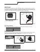
Mounting Options Wall Mount The VMP-2000 has a wallmount bracket specifically design to mount the printer to a wall or bulk head in a vehicle. This installation is designed to pull paper from a free standing box or can utilize the VMP paper tray. Please review the specific instruction sheets for assembly and installation of the VMP-2000 Wallmount Bracket Kit (part # 110114-xxx).
Mounting Options Other The VMP-2000 paper tray is specifically designed to hold a box of standard tractor pin feed media for 8 ½” x 11” media. The tray can be mounted underneath the wall mount bracket. Please review the specific instruction sheet for assembly and installation of the VMP-2000 paper tray (part # 110098-xxx).
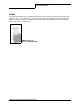
Mounting Requirements Mounting Requirements 19” 9” 3.5” 4.5” (without bracket) 12 - 15” Use the following information as a guide for orienting and/or mounting your printer: 1 Before mounting the VMP printer, review the documentation supplied with the bracket you choose to use. 2 The VMP printer can only be mounted based on the angles shown above. Mounting the printer outside of these angles results in the printer jamming.
Mounting Requirements Mounting Guidelines: • Do not position the printer above, near, or relative to, the driver's position as to interfere with normal driving operations. • Position the printer so it is protected from environmental elements such as moisture, tools, and boxes. • Do not set, place, position, or put any object(s) on top of the printer, either when the vehicle is moving, or when the vehicle is stationary.
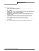
Input Power and Connection Requirements Input Power and Connection Requirements The VMP printer comes with one 12 volt DC jack cable with white collar or tag (external).
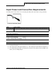
Input Power and Connection Requirements Printer Input Power and Connection Requirements There are several ways to connect the VMP to vehicle power — fuse box power cable, alternate cabling, existing power harness installations, and cigarette lighter adapter. Fuse Box Power Cable (part # 220210-100) Fuse Box Cable To properly install the fuse box power cable, review the MF8i Truck Mount Extension Cable Instruction Sheet (part # 110128-xxx) supplied with this cable.
Input Power and Connection Requirements • At a minimum, secure cables every 12-18 inches. • Allow an adequate 12” loop for connector and disassembly cable. Existing Power Harness Installation (part # 220205-100, 220206-100, 220207-100) The power extension cable is available in lengths of three feet, six feet, and ten feet. If your vehicle has an existing cable power harness from a previous printer installation, it may be used to connect to the VMP printer by using the power extension cable.
Input Power and Connection Requirements Once connected, use a volt meter to ensure that the center pin on the DC jack is positive (+) 12 volts and with specifications for input voltage. Note: DO NOT connect to the printer if the center is not positive 12 volts. You will damage the printer. Cigarette Lighter Adapter (part # 510116-000) You can connect the cigarette lighter adapter to any universal 12 volt cigarette lighter plug.
Data Connection Data Connection The VMP has a DB-9 RS232 data connection. This cable is designed to plug directly into a handheld computer cradle dock, or other standard RS232 interface with no cabling required. If you choose to cable connect your computer or handheld device to the printer, contact Datamax-O’Neil for the latest cable list. If you choose to install your own cabling, see the diagram below for cable pin outs and design.
Data Connection Power Supply The VMP can run solely from a power supply. For more information, see Input Power and Connection Requirements on page 8. Use only the Datamax-O’Neil approved power supply. Power Supply Requirements • Use the Datamax-O’Neil recommended power supply. FAILURE TO USE A DATAMAXONEIL WILL RESULT IN DAMAGE TO THE PRINTER OR THE PRINTER WILL NOT OPERATE PROPERLY. Note: The operating temperature of this portable printer is 50° C.
Ribbon Information Ribbon Information The VMP ribbon is designed to provide hundreds of pages of use. However, the ribbon is a consumable item and should be replaced often. • If the printer begins jamming consistently, replace the ribbon. • If the printing becomes light in color on the top copy, replace the ribbon. • If the smear guard is damaged or lost, replace the ribbon.
Printer Settings Printer Settings If you begin to see print head jams or the paper is catching under the print head when in the ‘home’ position, you may wish to change the print head centering setting or skip over perforation. Print Head Centering The VMP printer has the ability to control the print head location when the media moves across the media’s horizontal perforation. The default setting is ON when the printer is shipped from the factory.
Media Specifications Media Specifications Paper Guidelines Media Quantity Original unlimited supply Original +1 unlimited supply Original +2 unlimited supply Original +3 unlimited supply Continuous Form Specifications Impact printers use continuous single-part or multi-part forms. The multi-part forms can have up to four parts. Single-Part Form Multi-Part Form Width 3” - 9.5” (76.2mm - 241.3mm) 3” - 9.5” (76.2mm - 241.3mm) Thickness 2.6 mil - 3.9 mil (0.065mm- 0.
Media Specifications Form Specifications Paper Size and Print Area Print Area Diagram Symbol Description A Paper Length: 11 inches (typically) (279.4 mm)/11.69 inches (A4)(297.0 mm) B Paper width: 3” minimum - 9.5” maximum C First dotline: 11.8 mm D Hole spacing: 12.7 mm + 0.5 mm E Vertical Character Alignment Tolerance: For adjacent line: 0.3 mm maximum in bi-directional printing For 10 lines: 1.5mm maximum F Maximum Print Width: 200.7 mm G 6.
Radio/Bluetooth Guidelines Radio/Bluetooth Guidelines • Radio communications are affected by metal and surrounding objects. • Consider the internal antenna location when mounting the printer. The range depends on the orientation of the VMP printer. • Contact your handheld computer manufacturer for setting up the printer for Bluetooth communications.