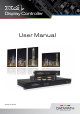
Display Controller U ser M a n u a l Version 01.03.
Contents Safety Instructions 3 Introduction 4 Configuration Examples 5 Unpacking 9 Description 10 Setting up the x4 13 Configuring the x4 14 Operating Instructions 16 x4 Control Application 17 Specification 26 Datapath Limited 27 Index 28 UK Headquarters and Main Sales Office 30
Safety Instructions To prevent damage to your Datapath product or injury to personnel operating the equipment, please read the following safety precautions prior to operation. These instructions should be made available to all those who will use and operate Datapath products. Power Supply All Datapath products require a mains power supply. This power supply must be disconnected when equipment is being upgraded or relocated.
Introduction The Datapath x4 is a stand alone display wall controller that accepts a standard single or dual-link DVI input and can flexibly display this across four output monitors. Each output can be driven as DVI or analog RGB, and can represent an arbitrary crop region of the original input image. The output resolution and frame rate does not need to be related to that of the input as the Datapath x4 will optionally upscale and frame-rate convert each cropped region independently.
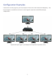
Configuration Examples Listed on the next few pages are just a few examples of what can be achieved with the Datapath x4.
Divide the input signal into quadrants and display each quarter on separate displays with optional frame rate conversion (in this case 30Hz to 60Hz). Crop regions can be adjusted to provide monitor bezel compensation.
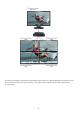
Duplicate the input signal x2 and display 1 on a single landscape display and divide the 2nd into thirds, rotate to portrait, upscale and split between 3 displays. Crop input signal, upscale specific areas and display on 4 separate screens.
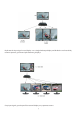
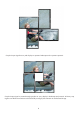
Crop the input signal into x4 and display x2 quarters landscape and x2 quarters portrait. Crop the input signal x4 rotate through 90º,180º or 270º, display in landscape and portrait. Arbitrary crop regions can allow the monitors to be artistically arranged, but maintain an undistorted image.
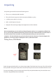
Unpacking Your packing box should contain the following items: • The x4 or x4-1U Display Wall Controller • The x4-PSU Power supply unit with international blades (x4 only) • 1 x Mains power cable (x4-1U only) • USB 2.0 cable Type A to Type B. • Datapath CD containing Configuration Application and User Manual. Note: We recommend that you do not discard the packing box until you are completely satisfied with the x4 and it is fully installed and working correctly.
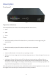
Description Front panel Fig.1 Operation Indicators The front panel has three LEDs to indicate the operational status of the x4: • Power • Input • Status Power • When illuminated, the Power LED indicates the x4 is connected to a mains supply using the supplied PSU. Input • When illuminated, the Input LED indicates a valid DVI source is connected. Status • Continuous illumination – Indicates the x4 is operating normally. • Flashing – Unit is operating over the normal operating temperature.
Output Framelock (x4-1U only) The Output Framelock is intended to ease the setup of the x4-1u by setting all four outputs to the exact same timings by replicating the the timings of the first output. Push and hold the button for approx 3 seconds to activate the Output Framelock. (The three LEDs will flash to indicate the operation is successful). If the first output is set to “Use The Monitor’s Preferred Mode”, the EDID timings will be sampled from the monitor, and written into the x4 defaults.
DVI-D Input Socket The DVI-D Input socket is used to connect the DVI input source to the x4. The x4 supports Dual Link DVI, Single Link DVI and also HDMI (not HDCP compliant) by using the optional DVI/HDMI Adapter. DVI-I Output Sockets The four DVI-I Out sockets are used to connect the x4 to the output monitors. The x4 supports both DVI and analog RGB monitors. Power The Power socket is where the power source is connected to the x4. The x4-PSU supplied is plugged into the Power socket.
Setting up the x4 • Ensure the power supply for the DVI source is disconnected. • Connect the cable from the DVI source to the input socket on the rear of the x4. • Connect the four displays to the output sockets on the rear panel of the x4. • Connect the x4-PSU to the x4 and switch on the power supply at the mains socket using the correct international blade (see page 9). • Power up the DVI source.
Configuring the x4 Factory Default Settings The x4 stores a number of parameters to configure its operation. This allows it to operate stand alone in a very flexible manner. The configurations affect the input and output display modes as well as the required partitioning of the input image between monitors.
Whenever the monitor EDID is used, the x4 will calculate the internal scale factors to ensure that the monitor (at whatever resolution it is being driven) will still display the correct proportion of the input image. If an EDID cannot be read (for example if the monitor cable does not support the DDC signals required), there is a default mode that can be programmed into the x4’s memory. This is factory configured to 1080p.
Operating Instructions DVI Input When the X4 is powered up successfully and the Power, Input and Status LED indicators are illuminated; this indicates that a DVI input mode has been detected and is working normally. If the Input LED indicator is not on, check to ensure a single or dual link DVI cable is correctly fitted to the appropriate sockets. At high resolution, DVI signals cannot normally be guaranteed beyond 5m cables due to the nature of the signal losses inherent in the DVI cables and connectors.
x4 Control Application Application Installation Note: Do not plug the x4 into a USB port until the driver installation is complete. Locate the Install folder on the Datapath CD supplied with the x4, run install.exe. and follow the installation wizard. During installation a warning message is displayed stating that the driver does not have Windows® Logo accreditation. Select Continue Anyway to complete the installation. The Datapath x4 can now be connected to a suitable USB 1.0 or 2.
The main control dialog is divided into the following groups: Connection Diagram DVI-D Input Input Capture Regions Device Monitor Outputs Connection Diagram The connection diagram displays a schematic view of the rear panel of the x4 to assist in identifying the connectors. Fig.5 Device The unique USB device name that is connected is displayed in the Device group. It is possible to associate a more user friendly name such as “First Four Outputs”.
DVI-D Input The DVI-D Input group displays the current DVI mode that is being captured (if any) and the preferred mode that has been programmed into the x4’s EDID. Use the Modify button to update the EDID. The small square to the left of the current input resolution indicates whether the x4 has frame-locked to the input source. • Green – The outputs are frame-locked to the input dot clock and vertical sync • Grey – The outputs are not frame-locked Fig.
Fig.9 The DVI-D Input dialog displays the resolution of the current mode for reference and allows the timings of the EDID preferred mode to be edited. To populate the EDID timings with the current timings click on the Copy Timings button.
All modifications to the Input settings can be saved as part of a .vqs file, removing the requirement to input the same settings again. To save the settings select the Save… command in the File menu. To open a saved .vqs file select the Open… command. Limitations Fig.10 Figures entered as the Input EDID Prefered Mode may exceed the internal bandwidth limitation of the x4, if this happens a warning is displayed in the form of the figures being highlighted pink, as shown in Fig.
Input Capture Regions Each output of the x4 can select a different region of the input source image. This dialog (Fig. 11) displays the settings of each region (region 1 corresponds to output 1 etc). The numbers denote the top, left, width and height coordinates of the region that is to be displayed. Note that these are described in terms of the current active input resolution.
Predefined Regions For ease of use, there are preset buttons to select the two most popular configurations: Quarter or Replicate. Quarter The first monitor displays the top left hand corner of the input image, the second monitor the top right, the third the bottom left etc. This mode of operation can be used to drive four monitors in a 2x2 arrangement from a single high resolution input. Replicate Each output displays the entire input image.
Grey The outputs are NOT frame-locked. Fig.13 Individual monitor outputs can be configured by clicking on the corresponding Modify button. This will bring up a timing dialog similar to that of the input timings. This dialog is shown in Fig.14. Fig.
The source of mode selection controls whether the x4 output should take its timing values and resolution from the preferred mode of the monitor that is connected, or use its internally programmed ‘default’ mode. Please note that only the internal default timings can be edited in this dialog. If Use the Monitors Preferred Mode is selected, but no valid EDID can be read from the attached monitor, then the x4 firmware will program the output using the default mode timings.
Specification Physical Dimensions x4 - 235 x 175 x 44mm/9.25” x 6.9” x 1.75” x4-1U: 438 x 173 x 40mm/17.24” x 6.81” x 1.57” 0 - 35 DegC/32 - 96 DegF 5V DC, 18W. Universal mains power adapter supplied (100-240V) Operating Temperature Range Power Requirements Datapath x4-1U: Internal PSU The unit contains a cooling fan. The input and output vents should not be restricted Full speed (12Mbits/s) operation supported To 330 Mpixels/s 4k x 4k maximum To 165Mpixels/s Up to 2.
Datapath Limited Datapath has a long and very successful history in the computer graphics industry. Datapath has been designing and supplying high performance, high quality graphics display systems to the world’s largest and most demanding companies and institutions since 1982. Datapath was one of the founding companies of multi-screen Windows acceleration using single and multi board solutions.
Index A H Application Installation 17 Hardware wizard 17 arbitrary crop 4 HDMI 12 B I bezel compensation 6 Input LED 10 C Input socket 12 cables up to 20m 19 Input Surface 26 configuration 14 L Configuring the x4 16 LED’s 10 Connecting the x4 13 Limitations 21 connection diagram 18 M Cooling 26 Mac OS 14 Copyright Statement 27 mirrored 4 Crop regions 6 Models Available 26 D Modify button 23, 24 Default Settings 14 Monitor Outputs 23 device name 18 O display orientations 5
Power Supply 3 PSU Blades 9 Q Quarter 23 R Rear Panel 11 regions to be displayed 15 Replicate 23 rotate to portrait 7 S safety precautions 3 Scaling Optimisation 23 Single Link DVI 12 Status 10 Status LED 10 Sync sockets 11 T Technical Support 27 Test button 25 test patterns 25 U UK Headquarters 28 upgrading your x4 25 Up Scaling 26 USB socket 11 W Warranty 26 Windows 17 Windows 7 20 29
UK Headquarters and Main Sales Office Datapath Ltd., Alfreton Road, Derby, DE21 4AD, UK Tel: +44 (0) 1332 294441 Fax: +44 (0) 1332 290667 Email: sales@datapath.co.uk www.datapath.co.