
Data Sheet
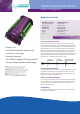

Technical Specifications
Connections to Logger
Digital control connections: 5D & 6D in/out terminals
Power Connections: 12V & DGND twin terminals
Analog Connections: *,+ ,- ,#
Each CEM20 attached to a logger uses a separate 4 wire
analog channel on the logger.
Maximum distance between logger and last CEM20: 100m
Maximum number of CEM20 units per data logger:
DT80 Variants (Series 2 and above)
DT85 Variants (Series 2 and above)
Multiplexer
Type: Relay multiplexer
Maximum Input Voltage: 30Vdc
Maximum Sampling Speed: 12Hz
System
Status LED: Sample activity
Address Selection: 4-way DIP switch. Address 1-15
Power Supply
Recommended: Logger’s switched 12V output
Alternative: External regulated 12Vdc ± 5%
Power Consumption
Sampling: 0.36W (12V 30mA)
Idle: CEM20 is automatically turned off when not sampling.
Physical and Environment
Construction: Powder coated steel and anodized aluminium
Dimensions: 180 x 100 x 50mm
Weight: 0.55kg
Temperature Range: -45°C to 70°C
Humidity: 85% RH, non-condensing
Assessories Included
Analog and control cables for connection to the
dataTaker data logger.
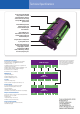
Diagram shows functional connections
for DT80 data logger and two CEM20
units. Cable lengths should always be
kept as short as possible to minimise
noise and signal losses.
DT80 data logger
CEM20
(Address=1)
CEM20
(Address=2)
12DV
DGND
12DV
DGND
12DV
DGND
12DV
DGND
12DV
DGND
Analog Out
Analog Out
5D
6D
5D in
6D in
5D in
6D in
5D out
6D out
5D out
6D out
1 2
1 2
1 2
Internal RTD temperature
reference allows very
accurate thermocouple
measurements.
Status LED indicates
measurement activity and is
a useful commissioning and
troubleshooting aid.
Simple address configuration
by 4-way DIP switch.
Proven relays from the DT80
range provides excellent
isolation between channels
and resistance to over voltag
damage. Maximum sample
speed is 12Hz.
20 analog input channels for
sensors supported by DT80
range loggers, includes
thermocouples, VWSG,
RTDs, 4-20mA loops, voltage,
resistance, frequency etc.