
Instructions

UM-0085-B09 DT80 Range User Manual Page 25
RG
Digital Channels – Introduction
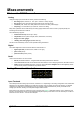
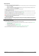
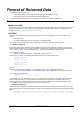
Figure 6: DT80 digital terminals
The DT80 provides:
• 4 bidirectional digital I/O channels (1D-4D) with open drain output driver and pull-up resistor (DT81/ 82E: 3
channels, 1D-3D)
• 4 bidirectional digital I/O channels (5D-8D) with tri-stateable output driver and weak pull-down resistor. These
channels may also be used for controlling intelligent sensors using the SDI-12 protocol (DT81/ 82E: 1 channel,
4D)
• 1 voltage free latching relay contact output (RELAY)
• 1 LED output (Attn)
• 4 hardware counter inputs (1C-4C) which can be used as independent counter channels or as two quadrature
(phase encoder) inputs (DT81: one phase encoder input, shared with inputs 3C and 4C. There are no phase
encoder inputs on the DT82E)
As with analog channels, channel definition commands are used to specify which digital inputs are to be measured
and/or what digital output states are to be set. For example, the command
1DS will read the digital state (0 or 1) on
channel 1D, while
3DSO=0 will set channel 3D low.
A transition on a digital channel can be used to trigger a schedule. This allows a series of measurements to be made (or
commands executed) in response to a change in digital state.
The DT80 can count the number of pulses received on any digital input. The four dedicated counter inputs provide
additional capabilities:
• a higher maximum count rate
• the ability to keep counting even if the logger is in low-power "sleep" mode
• optional low-level (5mV) input threshold levels
• optional decoding of phase-encoded input signals
For more details, see Digital Channels (P331)
Serial Channels – Introduction
The DT80 supports two main classes of "smart sensor":
• A wide range of sensors, particularly in the environmental monitoring field, use the SDI-12 protocol. The DT80
fully supports this protocol making it a simple process to read measured values. See SDI-12 Channel (P362).
• The DT80 also provides a generic serial channel.
The serial channel allows a wide variety of sensors and devices to be controlled and polled. The serial channel:
• can use the dedicated serial sensor port (not DT81/82E), the host RS232 port (not DT8xM), and/or the USB port
• supports USB, RS232, RS422 and RS485 signal levels (depending on the port)
• supports point-to-point or multi-drop operation (point-to-point only for the host/USB port)
• features programmable output (poll) strings and a variety of options for parsing returned data
• can trigger execution of a schedule in response to received data
For more details, see Generic Serial Channel (P348).