
Instructions


UM-0085-B09 DT80 Range User Manual Page 291
RG
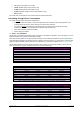
Parameter P28 is used to control the behaviour of the 12V or 12V/ 5V output.
P28
Description
Scenarios
P28=0
default
Auto CEM20 power control: DT80 ensures that 12V is switched
on prior to execution of a schedule that contains CEM20
channels. 12V will be switched off at the end of the schedule
(unless there is another schedule due which requires it)
12V output is used to power CEM20s
P28=1
12V output is switched on all of the time
12V output is used to power other equipment
12V output is used to power CEM20s and you wish to
avoid the 50ms warm up delay which occurs each time
the 12V output is switched on
P28=2
12V output is switched on all of the time, even when asleep
12V output is used to power other equipment which
needs to remain powered even if DT80 is asleep (e.g.
a dial-in modem)
P28=3
12V output is not changed
12V output to be controlled explicitly, using
PWR12V=
CEM20s are assumed to be independently powered
Controlling 5V Isolated Power Output
Only series 3
Use
PWR5V=1 to switch on the isolated 5V power output, and PWR5V=0 to switch it off.
Note: The 5V output is derived from the analog power supply, so it will only be on if the analog section is powered. By default, the DT80
analog section is only powered while a measurement is being taken. If you require the 5V output to be on continuously then it is
necessary to set
P21=1 so that the analog section is continuously powered. See Analog Measurement System (P298) for more
details.
Signal Output
Only series 4
Signal output (0-10V or 0-20mA) can be generated by series 4 logger. This is an additional feature which useful to give a
feedback to other devices.
Controlling voltage/ current outputs
On Series 4 loggers V/I DAC terminal replaces the 5V SW terminal which used to be on Series 3.
The V/I DAC terminal provides independent 16-bit resolution voltage/current isolated analog outputs.The current outputs
can be set within industrial standard output range of 0-24mA and voltage outputs can be from minimum 10mV to
maximum 10V. The DAC output can be used as an external voltage and current excitation source for many analog
sensors. It can also be externally routed to EXT* datataker terminal.
By using
VDAC or IDAC channels type you can set the desired voltage or current at the V/I DAC terminal. The
following expression
VDAC=1300 will set the output voltage to 1300mV while using IDAC=4 set the output current
to 4mA.
The V/I DAC output is independent power source and it will be on if even the analog section of the DT80 is not powered.
Use DAC=OFF command to switch the DAC off. The DAC power output is isolated fron the digital ground , the return
terminal for the DAC converter is AGND.
Internal Memory-Backup Battery
In addition to the internal main battery, the DT80 contains a small lithium "memory-backup" battery.
The memory-backup battery maintains the DT80's clock/calendar and certain memory settings. (Note that the DT80's
internal file system, which stores programs and logged data, uses non-volatile flash memory. This does not
depend on
the memory-backup battery).
Replacing the Battery
Under normal operation the memory-backup battery should last approximately five years, or approximately one year if
there is no other power to the DT80 (i.e. both external power and the main battery are disconnected).
See Inside the DT80 (P282) for details on how to remove and replace the internal memory-backup battery. The memory-
backup battery is a ½AA size 3.6V lithium type (for example, SAFT LS 14250). It’s important that 3.6V and not 3.0V
types be used (both types are the same physical size).
Storage
If the DT80 is to be placed in long term storage, it is recommended that the memory-backup battery be removed, to keep
it from discharging. When disconnected, the battery has a 10-year shelf life.