
Instructions

UM-0085-B09 DT80 Range User Manual Page 314
RG
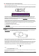
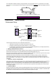
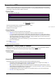
B3 – Multiple BGV Half Bridge Inputs
Note: The excitation voltage need only be measured once; it will then be used for all subsequent BGV channels in the same schedule.
In this configuration, three (or more) separate half bridges are wired in parallel so they share the same power supply and
completion resistors (Rc). This allows three separate bridge measurements to be made per input channel (plus one
channel to measure the excitation.)
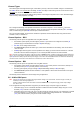
The excitation voltage is measured in the same way as for the 6-wire configuration. That is, it is either
• measured directly, using * and # terminals, or
• measured using the completion resistors as a 2:1 voltage divider, or
• assumed to be 5.00V
Then the half bridge output voltages (relative to the junction between the completion resistors) are measured using
separate analog inputs.
Figure 142: Wiring for multiple half bridges using shared external excitation
To measure
Use the command
3 x bridge outputs (3V supply)
1*V(BR,W) 2*BGV(N) 2+BGV(N) 2-BGV(N)
3 x bridge outputs (6V supply)
Connect 1* to Rc junction
1*V(2,BR,W) 2*BGV(N) 2+BGV(N) 2-BGV(N)
3 x bridge outputs (5.00V supply)
2*BGV(N) 2+BGV(N) 2-BGV(N)
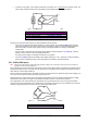
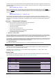
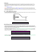
B4 – 4-Wire BGI Inputs
A current excited bridge is the recommended configuration for 4 wire bridge measurement, especially for bridges that are
distant from the DT80.
In this configuration the DT80's precision current source provides the excitation. To calculate the excitation voltage, the
DT80 needs to know the arm resistance, Ra, which is specified as the channel factor. The default is 350 Ω.
Figure 143: Wiring for 4 wire bridge input using internal excitation
To measure
Use the command
bridge output
1BGI(4W,R
a
)
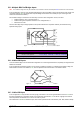
B5 – 3-Wire BGI Input
In this configuration Rc may be either an active gauge (if the strain on it is in the opposite direction to that on Ra and of
the same magnitude) or a completion resistor. For temperature compensation, Rc can also be a gauge which has the
same temperature characteristics as Ra but is not under any strain.
The resistances of Rc and Ra should be equal, and must be specified as the channel factor (max. 5kΩ, default is 350Ω).