
Instructions

UM-0085-B09 DT80 Range User Manual Page 204
RG
HANGUP Command
The HANGUP command causes the DT80 to instruct its modem to hang up (disconnect) the current dial-out or dial-in
connection. If there is currently no connection,
HANGUP is ignored. This can be used in an alarm action command to
cause the DT80 to hang up a call in progress when an alarm condition arises.
Example — Modem Control Commands
The use of the DT80’s modem control commands is demonstrated in the following program:
BEGIN"FLUFFY"
SETDIALOUTNUMBER"12345678"
RA10M
'Read boiler temp
1TK(=1CV,W)
IF(1CV>120){DIAL}
END
Every 10 minutes, the program checks the boiler temperature and then, if it exceeds 120°C, instructs the modem to
initiate a dial-out to phone number 12345678.
Modem Status
The System Variables 25SV (P40) gives an indication of the current state of the modem. It can be used with alarms to
determine the current state of the modem connection and to behave accordingly.
Modem Diagnostics
If you experience problems with setting up a modem, it can be helpful to switch on diagnostic messages by setting
P56=16. These messages are output to the active communications port and indicate events (e.g. DCD signal going
active) and DT80 actions (e.g. initialisation commands sent to the modem) as they occur.
Set
P56=0 to disable the diagnostic messages.
Setting Up a Remote Connection
The following is a brief summary of the steps involved in setting up a remote modem connection between the DT80 and
a host computer.
1. Pre-configure the modem as described in Configuring Your Modem (P201) and save the settings to the
modem's default profile.
2. Connect a local PC to the DT80 using a USB or direct RS232 connection and run DeTransfer/DeLogger.
3. Set the required profile settings to configure the host port and modem. For example:
PROFILE HOST_PORT FLOW_CONTROL=HARDWARE
PROFILE HOST_MODEM EXT_POWER_SWITCH=3DSO
will set hardware flow control (recommended), and configure modem power control using digital output 3D.
4. Connect power to the modem (in the above example the power would be supplied via a relay driven by 3D).
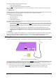
5. Connect a suitable comms cable between the serial port on the DT80’s modem and the DT80’s Host RS 232
port. This cable is normally supplied with the modem, see also DT80-to-Modem Cable (P200).
6. At the remote end of the link, connect a suitable comms cable between the serial port on the host computer and
the local modem.
7. On the host computer, configure the modem using the Windows control panel. It is recommended that hardware
flow control and an error-correcting protocol (e.g. V42) are used.
8. On the host computer, launch suitable terminal software, e.g. DeLogger or DeTransfer. Set up a connection to
use the modem.
9. Attempt to connect to the DT80 from the host computer.