
Instructions


UM-0085-B09 DT80 Range User Manual Page 333
RG
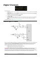
DI2 – Logic Inputs
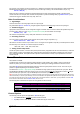
Actively driven logic signals can be directly connected to all input channels, provided that the input levels are within the
specified limits; see Input Characteristics (P381).
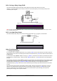
Figure 156: Wiring for reading TTL level signals on digital inputs
To measure
Use the command
state
1DS
(0 = low, 1 = high)
Other Considerations
Scan Rate
The digital input channels are scanned at 17ms intervals (60Hz), while the DT80 is awake. This means that the minimum
input pulse width is 17ms – shorter pulses may not be recognised.
Schedule Triggers
Digital input transitions can be used to trigger a report schedule, or a schedule can be configured to only run if a digital
input is in a particular state.
See Trigger on External Event (P53) for more details.
Sleep Mode
Digital inputs are not scanned while the DT80 is asleep.
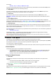
However, a high to low digital input transition can be used to wake the DT80 by connecting the digital input in parallel
with the WK (wake) terminal. The DT80 can then be programmed so that each time an external pulse occurs the DT80
will wake and run an event triggered schedule.
For example, if digital input 4 is also wired to the WK terminal then a typical schedule definition might be:
RA4-E 1..3TT
Note: the digital input must stay low until the DT80 is fully awake. A short pulse (less than about 1-2 seconds) will still wake the logger,
but the DT80 may not "see" the high-to-low transition, in which case the edge-triggered schedule will not run.
Digital Outputs
The DT80’s 8 digital I/O terminals (4 for DT81/82) can also be used as outputs, either individually, or as 4 or 8 bit words.
The following channel types are used to control the states of digital outputs:
Channel Type
Valid Channel Numbers
Description
DSO
1-8 (DT80/85)
1-4 (DT81/82)
Digital State Output: sets the state of digital output; 0=low, 1=high
DNO
1-5
(DT80/85)
1 (DT81/82)
Digital Nybble Output: sets the state of four consecutive digital outputs starting at the
specified output.
DBO
1
Digital Byte Output
: sets the state of all eight digital outputs.
RELAY
1
Relay Output
: sets the state of the latching
RELAY
output: 0=open, 1=closed
WARN
1
LED output
: sets the state of the
Attn
LED: 0=off, 1=on
For example:
7DSO=1 sets output 7D high
5DNO=5 (binary 0101) sets 8D low, 7D high, 6D low and 5D high
1DB=255 (binary 11111111) sets all outputs high
1RELAY=1 closes RELAY output contacts
Channel Options
The following channel options are applicable to digital output channel types:
• channel factor: for the multi-bit channel types (DNO, DBO), the channel factor is a bitmask which specifies
which digital outputs to alter. The default values for
DNO and DBO are 15 and 255 respectively (i.e. set all bits)