
Instructions


UM-0085-B09 DT80 Range User Manual Page 340
RG
For example, if the average counter input frequency is 100Hz then the DT80 must be programmed to wake at least every
65536/100 seconds (about every 10 minutes). This can be done by including a 10-minute schedule in the job, e.g.
RA10M 1HSC(W)
Most of the other comments made above regarding digital input counter channels apply equally to the high speed
counter channels. For example, HSC channels can be preset to a particular starting value (e.g.
2HSC=1CV*10), HSC
channels can trigger a schedule when they wrap, and so on.
Other Considerations
Signal Edges
Counters increment on the rising edge of the count input signal.
For gated modes (P27=1 and P27=2), the gate signal is sampled on the falling edge of the count input signal.
Schedule Triggers
High speed counter channels can be configured to trigger a schedule when the counter reaches its specified wrap value
(at which point it resets to 0). See Trigger on External Event (P53) for more details. For example,
RA2HSC(100) 1TK
will measure a temperature on every 100th pulse received on counter input 2C.
Presetting Counters
The count value for a high speed counter channel can be preset using an expression, e.g.
RA1M 1HSC=1000 RB2S 1HSC
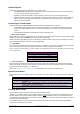
will reset the counter to 1000 once per minute. So if a 1 Hz signal is now applied to input 1C you would expect the values
returned every 2s for channel
1C to follow a sequence similar to:
1000, 1002, 1004 ... 1056, 1058, 1000, 1002 ...
Setting Counter Wrap Value
As with low speed counters, a counter’s wrap value (channel factor) is applied when the channel is defined (i.e. when the
job is entered), not when it is evaluated. Also, setting the wrap value has the side effect of resetting the count value to
zero. As discussed earlier, this implies that the wrap value should therefore normally only be specified once for each
counter channel.
Phase Encoders
Not available on DT82E
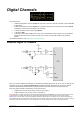
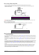
A phase encoder is a device for measuring relative angular or linear position. As it rotates or moves, it outputs two
streams of pulses ("A" and "B") whose phase relationship (A leading or B leading) indicates the direction of travel.
The DT80’s PE channel type decodes these pulses and returns a signed position value in counts. The count may be
positive or negative depending on the direction of travel.
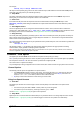
As mentioned in Counters – High Speed (P338
), the DT80's four high speed counter inputs are set up in pairs: 1C/ 2C
and 3C/ 4C; also 5C/ 6C on DT85/ 85L Series 3. Each pair can be used as either
two independent counters, or a single
phase encoder input. (For DT81, only the 3C/ 4C pair can be used as a phase encoder input.)
Note: the "mode" of a counter channel pair (i.e. whether it operates as two counters or a single phase encoder channel) is set when the
channel is defined (i.e. when the job is entered), not when it is evaluated. This implies that a particular counter input pair cannot be read
as a phase encoder value at one point in a job, and as a pair of counters at another. In other words, if your job defines a channel
1PE
then it should not also define channels
1HSC or 2HSC, and vice versa.
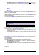
The following table summarises the options for using phase encoder channels:
Model
Channel
"A" input
"B" input
Notes
DT80/82/85
1PE
1C
2C
Do not use 1HSC and 2HSC channels
2PE
3C
4C
Do not use 3HSC and 4HSC channels
DT85/85L-3
3PE
5C
6C
Do not use
5HSC
and
6HSC
channels
DT81
1PE
3C
4C
Do not use 3HSC and 4HSC channels
Channel Options
The following channel options are applicable to PE channel types:
• the channel factor is not used for phase encoder channels
• R (reset): Position value will be cleared to 0 after returning its current value