
Instructions

UM-0085-B09 DT80 Range User Manual Page 368
RG
Technical Details & Troubleshooting
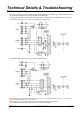
DT80 Analog Sub-System
This section provides some technical details on the internal operation on the DT80's analog measurement sub-system.
This will allow the interested user to better understand its characteristics.
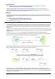
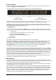
A simplified block diagram of the DT80/81's analog sub-system is shown below. In this diagram the circle-X symbols
indicate relay contacts which can connect or disconnect the indicated points.
Figure 168: DT80/ 81 Series 1 Analog Sub-System
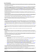
The DT80 and DT85's Series 2 analog sub-system is slightly different:
Figure 169: DT80/ 82/ 85 Series 2 Analog Sub-System.
Note1: Series 3 has the same circuit, except that 213uA current source can also be switched through to the *, + or – terminal. This
allows 2-wire resistance measurements on any terminal
Notes2: Series 4 has one more additional 2uA current source available for measuring high resistance
The following sections discuss the various points to note about these diagrams.