Digital Video Switcher SE-800 INSTRUCTION MANUAL Http://www.datavideo-tek.
Table of Contents Warnings and Precautions … … … … … … … … … … … … … … … … … … … … … … … … … … … … … 3 Warnings and Precautions Radio and Television Interference Declaration of Conformity Introduction… … … … … … … … … … … … … … … … … … … … … … … … … .
Using Transitions… … … … … … … … … … … … … … … … … … … … … … … … … … … … … … … … 35 Selecting a Transition: Fade, Wipe, Zoom Playing a Transition Manually Auto-play Using the Keypad to customize a transition Saving effects to Preset Bank Mode Selects and Use External trigger using GPI List of Transitions Using Effects… … … … … … … … … … … … … … … … … … … … … … … … … … … … … … … … … … 41 Selecting and customizing an effect Using the Keypad to customize an effect Freeze Misc, Strobe, Black and White Effects:
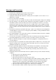
Warnings and Precautions 1. Read all of these warnings and save them for later reference. 2. Follow all warnings and instructions marked on this unit. 3. Unplug this unit from the wall outlet before cleaning. Do not use liquid or aerosol cleaners. Use a damp cloth for cleaning. 4. Do not use this unit in or near water. 5. Do not place this unit on an unstable cart, stand, or table. The unit may fall, causing serious damage. 6.
Radio and Television Interference UNITED STATES: The equipment described in this manual generates and uses radio frequency energy. If it is not installed and used in accordance with the instructions in this manual, it may cause interference with radio and television reception. This equipment has been tested and found to comply with the limits for a Class B digital device, pursuant to Part 15 of the FCC Rules.
Introduction Thank you for purchasing Datavideo’s SE-800 Digital Video Switcher. We think you will be amazed and pleased at what you can do with this advanced piece of technology. In order to get the most out of your new switcher, we recommend that you spend some time getting familiar with this manual, as it will describe in detail all the functions of this unit. In addition, you’ll find some useful background information on video and audio, and some detailed examples of ways to use your new switcher.
What is a frame synchronizer? A frame synchronizer is a digital device that stores a frame of video in its memory and releases it at a very precise moment. These little devices are essential if you want to make a seamless switch from one video source to another. If the sources you are switching between are not synchronized with each other, the video image falls apart at the transition moment, and the result is not pretty.
Tech support Datavideo maintains three offices worldwide to support this and other products. Datavideo Technologies Co., LTD. 7F, No. 352, Sec. 2, Chung Shan Rd Chung Ho City, Taipei Hsien, Taiwan R.O.C. Tel: 886-2-2246-7979 Email: info@datavideo.com.tw Datavideo Corporation USA 12300-U East Washington Blvd. Whittier CA 90606 USA Tel: (562) 696-2324 Email: contactus@datavideo-tek.
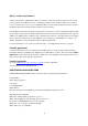
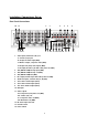
Installation, Connections, Set up Rear Panel Connections 1b 1a 2 3 6 7 8 4 5 11a 10 11b 11c 11d 12 13 1c 1d 1e 1. Video inputs, Channels A, B, C, D. 1a. S-Video (Y/C) input 1b. Composite video input (BNC) 1c. Monitor output, composite video (BNC) 1d. Component (YUV) video inputs (BNC) 1e. DV input (Firewire 6-pin with cable power 14.5VDC) 2. SDI (SMPTE 259M) Overlay input (BNC) 3. SDI (SMPTE 259M) Overlay out (BNC) 4. SDI (SMPTE 259M) Out (BNC) 5. DV output (Firewire 6-pin with cable power 14.
1. Video In (Channels A, B, C, and D are all set up the same way) a. S-Video (Y/C) input: takes a standard 4 pin S-video cable from the output of a VCR, camera, DVD player, etc. b. Composite video input: takes a BNC connector from the composite output of a VCR, camera, DVD player, etc. c.
8. Audio Output: Two RCA stereo pairs of line level analog audio, carrying the signal present at the output of the audio mixer section (see Controls and Operations, page 22). 9. GPI input: 1/8-inch (3.5mm) mini jack for remote trigger control. For more information, see GPI Trigger and External Trigger Using GPI on page 14. 10. Video Output. These ports carry the Main video output of the SE-800. a. Y.U.V.
16. Headphones: accepts a stereo 1/4 inch plug for stereo headphones. The signal present at the Headphones jack is controlled by the Headphone controls switches and level on the front panel. For more information, see Controls and Operations page 22 and Output and Monitor, page 13. Some General Notes on Installation There are a few other things to be aware of when you are installing and integrating the SE-800. Please make sure you have read the Warnings and Precautions section on page 3.
Power up State When you first power up the SE-800, you will need to make channel assignments and set audio levels. Transition and effect settings are not retained please refer to Preset Bank on Page 35 for function keys setup (see Using Transitions, page 35 and Using Effects, page 41 for details). At power up, channel A will be the selected Main Video Source and channel B will be the selected Sub Video Source.
RCA plugs (also sometimes known as phono plugs, cinch, or tulips) are used for line level audio, such as the connections between a CD player and amp. The SE-800 uses these in stereo pairs, white for left and red for right, at the audio input and output sections. 1/4 inch jack plugs got their name, some say, because they used to be used to manually patch together phone lines in the old central switchboard days.
Using SE-800 SDI Overlay interface for CG Text overlay Using SDI interface (270 Mbps, SMPTE 259M standard) and the EXT Chroma-Key effect on SE-800 to communicate with a PC SDI CG overlay card and perform a text overlay for the output video, page 45. GPI Trigger A GPI (General Purpose Interface) trigger is connected here by means of a mini plug (1/8”). This device allows you to make the SE-800 do certain things at the specific moment you press the trigger, such as making transitions and effects happen.
Quick Start We’ve made three sample application set ups for using the Switcher: Production studio; Multi-camera event (city council meeting, church service, etc); and Performance (club VJ, concert visuals, etc.). Pick the one that most closely approximates your initial intended use, follow the block diagram to make the video and audio connections, and jump in to using the controls.
DV Camera 2 DV Camera 1 Preview Monitor 1 DV Camera 4 Connect CD Player or other tape player, for background music DV Camera 3 Preview Monitor 3 Preview Monitor 2 To DV Recorder Deck Preview Monitor 4 Moderator mic Council mic Audience mic From Audio Mixer, VCR… Multi-camera event: city council meeting Text on diagram: This multi-camera event could just as easily be a church service, Queen for a Day pageant, school play, or jazz concert; the general idea of the set up remains the same.
DV Camera on dance floor4 DV Bank 2 DV Bank 1 Preview Monitor 1 Connect CD Player for background music From Club Audio Mixer.
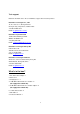
4 3 5 6 7 8 1 2 9 24 23 10 11 22 21 20 19 18 16 17 15 14 13 12 1. Audio meters 19. Cursor Keys 2. 3. Audio input selectors and level controls Joy stick and mode selector 20. Transition mode selectors 21. Audio faders 4. Main Video source selector 22. Audio Input channel selectors 5. 6. Sub video source selector Audio follow video switch 23. Headphone level control 24. Voice sync adjustment 7. Input format selector 25. Microphone input Left/Right 8. 9.
Selecting video input formats and adjusting audio levels (Numbers refer to the Front Panel illustration above) *. Verify that there is a valid source at each input you’ve connected by using the Main Source Select buttons (4.) to select a channel and view the output on the main monitor. For each input channel (A, B, C, D): press the top Input Format button (7.) to select the channel, then press the bottom button to select the proper video format. DV = digital video through FireWire (a.k.a.
Cutting between sources The simplest way to cut (switch) between source video inputs: use the Video Main Source buttons (4.) to select which input goes to the program monitor (output). Look at the results on your program or record monitor. Dissolving between sources Select the Main Video Source (4.) by pressing the appropriate channel button. The LED for the channel you have selected should be lit and you should see that source on the program monitor. Select the Sub Video Source (5.
pressing the up and down arrow keys; sizes are numbered 1-8 and displayed in the Effects window above the Keypad. Alternately, you can enter numbers 1-8 on the Keypad. There are 3 options for how much of the image is affected; PIP/Mosaic effect can be selected by pressing the PIP button in Mosaic mode, press the PIP “Up”, “Down” arrow keys for Mosaic/PIP picture size which can be positioned using the Joystick (3.).
Controls and Operations SE-800 Front Panel 4 3 5 6 7 8 1 2 9 24 23 10 11 22 21 20 19 18 16 17 15 14 13 1. Audio meters 19. Cursor Keys 2. Audio input selectors and level controls 3. Joy stick and mode selector 20. Transition mode selectors 21. Audio faders 4. Main Video source selector 22. Audio channel selectors 5. Sub video source selector 6. Audio follow video switch 23. Headphone 24. Voice sync adjustment 12 7. Input format selector (Setup video) 25.
1. Audiometers: LED style meters, which show the signal strength at the Audio Output. The signal they measure is determined by the sources selected by the Audio Bus selectors (22.) and the levels set by the Faders (21.). The LEDs turn red at +9 dB to indicate clipping distortion. For more information, see Audio Inputs, Levels, and Meters, page 32. 2. Audio Input Selectors and Level Controls: Controls which audio input channel (A, B, C, and/or D) is sent to the Audio Bus Video (VCR) channel (22.
6. A+V: Audio follow video switch. When this button is engaged (you’ll know it is engaged because the LED is lit), the audio associated with a selected input source automatically follows the video through the dissolve. When the button is inactive, audio must be switched manually. For more information, see A+V, page 34. 7. Input Format selectors: These buttons allow you to select the input video format for each channel.
11. Mode: selects the T-Bar operating mode of the SE-800, between Video (default), Audio, GPI, and Play. For more information, see Mode select in the Using Transitions section, page 35, and Mode select in the Using Effects section, page 41. 12. T-Bar: used to manually perform a transition. For more information, see Playing a Transition Manually, page 35. 13. Chroma Key: when engaged, this removes the selected color from the Main Video Source and reveals the corresponding portions of the Sub Video Source.
16. Mosaic: when engaged (and the Mosaic LED is lit), this turns the selected Main Source Video into a mosaic of colored squares. There are 8 mosaic patterns to choose from, selected by repeated presses of the up and down buttons. The effect can be applied to the whole image or one of two window sizes, which can be positioned anywhere on the screen. For more information, see Effects: Mosaic, page 42. 17.
21. Faders: sliders to control audio levels for the Main audio output mix. Each is active when the LED on the Audio bus selector button (22.) above it is lit. For more information, see Audio Inputs, Levels, and Meters, page 32. 22. Audio Bus selectors: the LEDs indicate which of the audio inputs are active in the Main audio output mix. Press the button to either include or exclude the channel. The left button, labeled Mic/Aux, can be set to either Mic, Aux, or off.
Video Source Selecting the Main and Sub Video Sources is the first thing to do when setting up the SE-800. The source you select (by pressing one of the buttons; a bright red LED on the selected button lights for confirmation) on the Main Source bus is what is sent to the Video output. This means that you can perform cuts between sources by simply pressing different buttons. (If A+V is engaged, video and audio from the selected source will switch together. See A+V, page 35 for more details on this function.
Input Formats This is the second thing to do when setting up your SE-800 for use: select the input format for each channel you’ll be using. These controls are active as soon as you push the upper channel select button. They become inactive when you have cycled through all 4 channels or when you press a button in any other control except the Color Processor.
(Brightness, Contrast, Color, and Tint) are pressed. U stands for Unity, or perhaps Unchanged. In either case, it shows that the signal passing through that particular control is being neither boosted nor cut. To see the settings for another control, press either one of that control’s buttons. To change the settings, press the up and down arrow buttons. You can see the extent of color processing available in this section by experimenting with the controls.
If you don’t have any video test equipment, follow the suggested procedure to adjust all the video sources, which is described at the end of Appendix: Monitor Calibration, page 55. Settings made in this section are “remembered” by the SE-800 after you power down the unit. In other words, these settings remain in effect until they are changed or either the Reset or the Reset All button is pressed.
Audio Inputs, Levels, and Meters (Headphone, faders, bus selectors,) These Audio Input Channel Selectors and Level pots are the first stage in the audio signal path. Each channel carries the audio associated with a video input. Analog audio comes in through the RCA connectors on the rear panel; audio from the DV input is converted to analog and passed to this bus.
These faders correspond to the selector buttons above and control the relative volume of each input in the master output as well as the master output level. They are called faders because they are used to decrease (rather than increase) the signal levels to make a balanced and pleasing mix. When they are set at Unity, at 6, they pass the audio signal through at the same level it was at when it entered this bus. This is why level setting at the Input Bus is so important.
Voice sync *. VOICE SYNC” function is only available to correct the Audio input from the selected “Video” (A, B, C or D) channel. When engaged, this control allows you to compensate for delays in the video as it travels through the various components, processors, and converters of the Switcher, so that the video maintains sync with the audio.
Using Transitions Transitions are the centerpiece of the SE-800’s functionality, sort of its reason for being. (Would the SE-800 still be a Switcher if it didn’t do transitions? This is the sort of philosophical question that will be dealt with in volume 2 of this manual: SE-800, an Observer’s Manual.) The SE-800 can do 4 kinds of transitions: cut, fade, wipe, and zoom.
Auto-play The Take-button automatically plays the selected transition between the selected sources. Parameters (effect variation and speed) are displayed in the windows above the Keypad. See the next section below for more information. Using the Keypad to customize a transition The windows at the top of this section display parameter data relating to the selected effect.
Mode selects and use The default mode for the SE-800, and the one you will use most often, is Video. In Video only mode (Video LED is lit), the T-Bar operates as expected and as described everywhere in this manual. In Video + Audio mode (Both LED are lit), the T-Bar switches Video and the Audio between selected sources. In Audio only mode (Audio LED is lit), The T-Bar switches Audio volume high/low of the selected source In GPI mode, transitions and effects are played by the trigger (see below).
5: Zoom off to lower left 6: Zoom on from lower left 7: Zoom off to lower right 8: Zoom on from lower right 9: Zoom off to center 10: Zoom on from center Wipe (works in conjunction with Border controls except Soft): 1: Horizontal wipe, top to bottom 2: Horizontal wipe, bottom to top 3: Vertical wipe, left to right 4: Vertical wipe, right to left 38
5: Horizontal compress, top to bottom 6: Horizontal compress, bottom to top 7: Vertical compress, left to right 8: Vertical compress, right to left 9: Right angle wipe off, lower right to upper left 10: Right angle wipe on, upper left to lower right 11: Right angle wipe off, lower left to upper right 12: Right angle wipe on, upper right to lower left 13: Right angle reveal, upper right to lower left 14: Right angle reveal, lower left to upper right 39
15: Right angle reveal, upper left to lower right 16: Right angle reveal, lower right to upper left 17: Vertical wipe, left and right to middle 18: Vertical wipe, middle to left and right 19: Horizontal wipe, top and bottom to middle 20: Horizontal wipe, middle to top and bottom 21: Vertical compress, left and right to middle 22: Vertical expand, middle to left and right 23: Horizontal compress, top and bottom to middle 24: Horizontal expand, middle to top and bottom 40
Using Effects The SE-800 is capable of producing a wide variety of digital effects. These fall into 2 categories: single channel and dual channel effects. Single channel effects are produced on the source selected in the Main Video Source bus and need no second video input. Single channel effects include Strobe (MISC), Freeze, Mosaic, and Paint. For example, select any input channel having a valid signal as the Main Video Input. Press the Freeze button once.
Freeze This effect freezes the incoming video, as selected on the Main Video Source bus. Simple as that! There are no parameters, no variations. Press the button once, and the video freezes, press it again, and it returns to the selected source in full motion. The Freeze effect is single channel, and can work in conjunction with any transition. MISC MISC Mode will have more features added.
1 = large window is the affected area 2 = small window is the affected area To position the Mosaic window effects, press the button under the Joystick until the LED for Position Control is lit. Then you can use the joystick to position the effect in real time, anywhere on the screen. When you exit the effect, the position will be remembered as long as the Position Control LED is lit. This means that the next time you activate the Mosaic effect; the position will remain the same as previously.
Border These controls are used in conjunction with the Picture in Picture Effect and the Zoom and Wipe transition only, and can only be activated when either the Picture in Picture or Zoom control is active. With the On button’s LED lit, parameters for Style, Color, and Border Softness can be set by pushing the appropriate button. There are 2 Styles available: thin and thick. These choices are cycled through at each button press.
Chroma Key When engaged, Chroma Key removes the selected color from the Main Video Source and reveals the corresponding portions of the Sub Video Source. To engage this effect, select sources in the Main and Sub sections. Then, press the Chroma Key button once to select video as the key overlay (INTL LED will light), press a second time to select EXT (LED is lit) for PC/MAC SDI CG overlay, and a third time to select both.
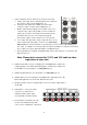
Production Studio: Cable news/weather show Connect Studio Mixer, VCR Studio Camera on weather talent with green/blue screen Video Pass thru to a preview monitor or Datavideo TLM-404 4”x4 TFT LCD Display Studio Camera on Anchor Connect DV input sources, such as Datavideo DV Bank for background video Connect CD Player or other tape player, for background music Weather talent mic, Anchor mic To Master Recorder Deck Connect a program Monitor The block diagram for this example shows a typical set up in a
Multi-camera Shoot: A City Council Meeting DV Camera 2 DV Camera 1 Preview Monitor 1 DV Camera 4 DV Camera 3 Preview Monitor 3 Preview Monitor 2 To DV Recorder Deck Preview Monitor 4 Connect CD Player for background music Moderator mic Council mic Audience mic From Audio Mixer, VCR… This example takes us on a location shoot, to record an important city council meeting, with numerous speakers. The event is being covered by 4 cameras, each connected to the SE-800 by DV cables.
Live Event Mixing: Club VJ DV Camera on dance floor4 DV Bank 2 DV Bank 1 Preview Monitor 1 From Club Audio Mixer. DVD Player Moderator mic Audience mic To club video system Preview Monitor 3 Preview Monitor 2 Connect CD Player for background music To VTR recorder and program monitor Preview Monitor 4 Our final example set up takes us to club land, or some place like it, for a live performance of video and image mixing.
These set ups can be modified for use in a lot of different situations. Please let us know how you are using your SE-800, and take a look at the web site to see how others are using their SE-800s! Troubleshooting No power No image at output Audio clipping Audio or video feedback Frozen image at output Image distortions l No power 1. Check the contact of power connector. 2. Move the SE-800 to a cooler location and allow the unit time to cool off before powering on again. l No image at output 1.
Appendix Glossary of Terms analog video: a video signal that is recorded and played back using changes in magnetic levels recorded on a tape or disk, e.g., the video we see when we watch a VHS videocassette. MISCation: a video or film sequence that gives the illusion of motion by presenting a series of images or photographs.
frame synchronizer: a digital buffer that stores a frame of video, compares the sync information to a reference, and releases the frame at a specific time to adjust for timing errors. glossary: a list of difficult or specialized words for reference. GPI: General Purpose Interface, a simple trigger device. hue: a specific color; one of the 3 attributes of color, see also saturation, brightness. IEEE1394: a low cost digital interface that can transport data at up to 400 Mbps. impedance: A.C.
sync: electronic pulses that synchronize the scan rates of different components (cameras, recorders, switcher, etc.) in a video system. THD (Total Harmonic Distortion): Of a signal (most often audio), the ratio of the sum of the powers of all harmonic frequencies above the fundamental to the power of the fundamental, usually expressed in dB. Useful measurement of the accuracy of an amplifier or signal processor.
Tech Notes Books are written about many of the topics below, large and complex books. Look for them if you want more information than what we have presented here. What we want to do here is to provide a bit more in depth information, deeper background, on some relevant topics, and give you a framework for further technical investigations. Video Standards, Formats, and Quality Video standards refer to the broadcast and/or viewing systems; they are specific to certain regions of the world.
The point of all this technical information is ultimately to help you to make high quality video: video that looks good and serves the purpose for which it is made. But how do we know if the video is of high quality? And what does that really mean? There are certain technical standards that video must meet simply in order to be viewable on a monitor. And beyond that fairly cut and dried realm is the area of aesthetics.
broadcast systems between NTSC and PAL, but much of the usage will be the same. You can use the SMPTE bars regardless of where you are and what video system you are producing for, just as you can use EBU bars wherever. You’ll notice that the EBU bars don’t have the gray scale information The first thing to do is to get the color bars displayed on the monitor you want to calibrate. And then, locate the image controls on the video monitor, as these are the ones we will be adjusting.
For each input you plan to be using, have a valid signal and adjust the Color Processor controls on the SE-800 in this order: 1. Set contrast to midpoint; turn color all the way down so that the image is gray; 2. Adjust brightness until the image shows shadow detail and no blown out highlights; 3. Adjust contrast until just before the highlights bloom; 4. Bring the color control back to its midpoint; adjust hue so that the skin tones look natural; 5.
Signal Flow Schematic Error Codes rAE:RAM check error. EPE:EEPROM check error. WPE:write EEPROM error. EnE:video encorder error. brE:black_burst encoder error LdE:Load Program error.
Specifications Video Formats Analog Y/C, Composite CCIR601 NTSC and PAL (PAL and NTSC are separate models) Analog Y.U.V. Video; Sony Betacam standard DV interface, format at Y.U.V. 4:1:1 NTSC (or Y.U.V. 4:2:0 PAL), 25Mbps bit rate Video Inputs 4 – DV, Component, S (Y/C), Composite Video Output 1 – DV, Component, S (Y/C), Composite 1 – SDI Output Audio Inputs 4 – Video sources A to D, Music, Aux., Stereo Microphone Audio Output 2 Stereo main outputs and 1 stereo headphone (with volume control) 0.
Digital Y.U.V. Interface SDI (SMPTE 259M-C 270Mbps) Color Processing Brightness +/-10% Contrast +/- 3dB Color +3/-10dB R.G.B. White Balance: +/- 10 Degrees Video Bandwidth Component 5.2 MHz S (Y/C) 5.0 MHz Composite5.0 MHz DG, DP +/- 3%, 3 degrees Signal/Noise Ratio: Video > 55dB Audio > 65 dB Audio 20 to 20KHz +/-3dB Audio THD <1% Dimensions W x D x H 17" x 16.8" x 4.72" 430m/m x 420m/m x 120m/m Weight 13.8 lb, 5.
Useful Accessories from Datavideo Datavideo TLM-404 4”x4 TFT LCD panel Datavideo TLM-404 is a 4x4” TFT LCD monitors, 2U height design for standard 19" rack mount. NTSC/PAL video format auto recognition with video pass through 75-ohm self-terminated video output connector. The "AUX" input provides options for external format converters such as SDI and DV input converter.
Datavideo RMC-90 Remote Control Panel RMC-90 is a Remote Control Panel specially designed to work with SE-800 control panel simultaneously. RMC-90 provides a wired remote function of video channel selection keys, programmable effect function keys, T-Bar control… most of the control key functions from SE-800. It includes a Tally control for the Datavideo TLM-404 LCD panels and three GPI triggers to control Datavideo DV Bank.
Datavideo BAC-03 Balanced-Unbalanced Audio converter The BAC-03 is a bi-directional unbalanced to balanced and balanced to unbalanced audio converter, with four independent amplifiers providing stereo audio input and output.
The new functions for unit’s serial number #0305000427 and after In order to have these new functions, there are three firmware ICs need to be changed, which are System ROM-A: V5.2 or higher System ROM-B: V2.1 Video in boards (There are 4 channels Video input boards in SE-800): V5.0 Please Note: The items 1) to item 8) below are ROM-A (V5.2) and ROM B (V2.1) related function, only the item 9) is Vin (V5.0) related function. You may change it accordingly. The new firmware enables new features as below: 1).
2). On performing an effect transition, the selected A, B channel’s LED indicators on Main Source will both be turned on. 3). During SETUP the video format type for channel A, B, C, D, you may select the main source output accordingly to enable the video output to TV display. 4). Selectable DV Audio On/Off This feature enables you to separate DV Video input source with or without DV audio Operation procedure: S1. Click on Setup button to select channel A, B, C or D S2. Select Effect: “01” and “Enter” S3.
5). Selectable AGC ON/OFF control Procedure to turn Off/On the video input Auto Gain Control (AGC) S1. Click on Setup button to select channel A, B, C or D S2. Select Effect: “02” and “Enter” S3. Click on the “SPD” key to toggle speed LED display “Y” (with AGC control) or “N”(without AGC Control) S4. Click on SETUP button to exit and save the setting condition. 6). Adjustable video position (about 50 lines up or down) for external SDI overlay video.
7). Internal Chroma- Key ON/OFF control To turn Off/On internal Chroma-key function for application of EXT SDI CG overlay. S1. Click on SETUP button to cycle 4 channels LED on. S2. Select Effect: “02” and “Enter” S3. Click on the “SPD” key to toggle on speed LED display “Y” (Enable Chroma-Key) or “N”(Disable Chroma-Key) S4. Click on SETUP button to exit and save the setting condition. 8). Consistency A/V LED for T-Bar Cross Effect.
SE800 RS-232 Remote Control Command VER: 1.2 Released date: Dec-01-2003 1 Physical layer 1.1 Control output format: RS-232C 1.2 Communication rate: 57600 BPS 1.3 Data format: 8 bits serial, LSB first, 1 start bit, 1 stop bit, odd parity 2. Data link layer 2.1 Frame format 1st 2nd Header ID 3rd 4th 5th 6th 7th Length Data0 Data1 Data2 Data3 ,,, ,,, Last-2 Chksum_L Last-1 Chksum_H 1) Header Code consisting of one byte for frame synchronization.
3. Application layer The application layer designates the command structure and contents. 3.1 Command data format 4th 5th 6th 7th 8th 9th 10th 11th … Command Operated Operated Operated Operated Operated Operated Operated … group #0 #1 #2 #3 #4 #5 #6 1) The command group 03h(base 16) = SE800 control command 2) The operated refer to section 4. 3.
5.
38h = key_8 39h = key_9 3ah = key_enter 3bh = key_speed 3ch = key_up 3dh = key_down 3eh = key_left 3fh = key_right 40h = key_mosaic 41h = key_mosaic_up 42h = key_mosaic_down 43h = key_paint 44h = key_paint_up 45h = key_paint_down 46h = key_pip 47h = key_pip_up 48h = key_pip_down 49h = key_chromakey 4ah = key_chmky_clr_up 4bh = key_chmky_clr_down 4ch = key_chmky_lvl_up 4dh = key_chmky_lvl_down 4eh = key_input_format_ABCD 4fh = key_input_type_select 50h = key_brightness_up 51h = key_brightness_down 52h = key_
6. The return parameter of SE800 control command status th 5th 6th 7 8th 9th 10th 11th 12th Parameter Parameter Parameter Parameter Parameter Parameter Parameter Parameter #0 #1 #2 #3 #4 #5 #6 #7 Error code Effect Effect LED1 LED2 LED3 LED4 LED5 No. Speed 1) The error code 01h = Time out (over 15ms) 02h = length error 03h = checksum error 04h = not support command 05h = operated error 2) The effect No. The value from 0 to 99(63h) 3) The effect No.
Bit3 of LED5 = LED of key_f4 Bit4 of LED5 = LED of key_f5 Bit5 of LED5 = LED of key_f6 Bit6 of LED5 = LED of key_f7 Bit0 of LED6 = LED of key_f8 Bit1 of LED6 = LED of key_f9 Bit2 of LED6 = LED of key_f0 Bit3 of LED6 = LED of key_f10 Bit4 of LED6 = LED of key_f20 Bit5 of LED6 = LED of key_chormakey_internal (video) Bit6 of LED6 = LED of key_chromakey_external (PC) Bit0 of LED7 = LED of key_aud_a Bit1 of LED7 = LED of key_aud_b Bit2 of LED7 = LED of key_aud_c Bit3 of LED7 = LED of key_aud_d Bit4 of LED7 = LED
7.
74
All the trademarks are the properties of their respective owners. Datavideo Technologies Co., Ltd. All rights reserved 2004.