TW7000 Series HF Transceivers section 4 May 2012 Section 4–1
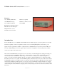
TW7000 Series HF Transceivers section 4 Features 1.6 to 30 MHz (100 kHz - Rx) Multi-mode capability 125W PEP/100W Average Multi-Protocol Remote Control Up to 1000 Preset Channels Internal BITE Embedded Voice Encryption Option MIL-STD-188-141B ALE Option Multiple Models- receivers, transmitters, and remote units Introduction Datron’s TW7000 series is a 1.6-30 MHz commercial HF transceiver family designed to provide long distance voice and data transmission capability over HF.
TW7000 SERIES HF TRANSCEIVER section 4 TW7000 Series Transceivers All models of the TW7000 are supplied with an operator’s manual. The technical manual must be ordered separately. 1. Transceivers with full-function front panels a. TW7000 b. TW7000PP TW7000 A SSB/FSK synthesized 1.6-30 MHz transceiver, (receive 100 kHz-30 MHz), 12 Vdc, 125W PEP/100W average (three programmable levels), USB, LSB, CW, and AME modes are standard.
TW7000 SERIES HF TRANSCEIVER section 4 TW7000TX A transmit-only version of the TW7000. Requires +12Vdc primary power input. It includes the dc power cable. Has full-function front panel. TW7000 Internal Options All of the options listed can be ordered either installed with the radio or added on later as a simple field upgrade to units already in use. Prices include factory installation at the time the radio is ordered. For field installation, contact your Datron Sales Representative.
TW7000 SERIES HF TRANSCEIVER section 4 PC-style keyboard can be used for message composition. All messages, whether transmit or receive, are displayed on the radio’s custom LCD display and stored in memory. 7000ALE FED-STD-1045A ALE module that provides a fully interoperable system for ALE operations, including highspeed scanning, sounding, link quality analysis, and send/receive AMD (“orderwire”) message capability.
TW7000 SERIES HF TRANSCEIVER section 4 7000RF An FSK modem for the 7000-series radios that allows communication with the RT7201F external FSK remote control head. It permits control of the radio remotely from the RT7201F Control Console over an audio 2-wire pair (with the radio being the “master”). Used when long-range remote control is required.
TW7000 SERIES HF TRANSCEIVER section 4 modem (long range) over a voice-grade 2-wire circuit. The TW7000 is also capable of full computer control from a PC. Both “remote-only” and “local-remote” configurations are available. The former configuration uses a radio with a blank front panel, while the latter uses a radio that has the normal full-function front panel to allow multiple control points. Remote control consoles include: 1. TW7201E 2. TW7201F 3.
TW7000 SERIES HF TRANSCEIVER section 4 1. RF Power Amplifiers 2. Power Supplies 3. Broadband Antennas 4. Narrowband Antennas 5. Automatic Antenna tuners 6. Audio Accessories 7. Mounting Kits 8. Miscellaneous Accessories 9. Data System Accessories 1. RF Power Amplifiers All amplifiers (except the DTX75000) are supplied less interface cables; the proper cables must be ordered separately. Amplifiers include: a. TW500D b. TW1000D c.
TW7000 SERIES HF TRANSCEIVER section 4 DTX75000 The DTX75000 5kW transmitter/transceiver contains a fully solid-state amplifier and offers the efficiency of class AB operation with the linearity of a class A design. It incorporates a sophisticated microprocessor-based controller and is composed of four separate 1250 watt sub-units that are combined to obtain the total 5kW power output.
TW7000 SERIES HF TRANSCEIVER section 4 RAT1000P-220 Identical to RAT1000P-110 except with NEMA 6-15P 220 VAC plug on power cable. Used in 500W or 1000W, 220VAC, high power systems whenever a 12 Vdc radio is used or when the radio-to-tuner control cable run exceeds 50 feet if used with a 28 Vdc radio. Order C991933 (control + power cable between the radio and the RAT1000P-220) and C991552 (control + power cable between the RAT1000P-220 and the RAT1000C) separately. Specify C991552 length. 3.
TW7000 SERIES HF TRANSCEIVER section 4 ABB1000A Broadband dipole antenna, 2-30 MHz, 1000 W, 144 ft (43.9 m). Standard length model provides better efficiency than shorter length model from 2-10 MHz. Supplied with 100 ft (30.5 m) RG213 coaxial cable and PL239 connector. Order AMX mast kit separately. ABB1000B Broadband dipole antenna, 2-30 MHz, 1000 W, 112 ft (34.1 m). Shorter length model for use where space is limited. Supplied with 100 ft (30.
TW7000 SERIES HF TRANSCEIVER section 4 MAR-12 Mobile whip antenna, 1000W, 12 ft (3.6 m). Three-section, heavy-duty fiberglass military whip with flexible spring base and mobile mounting bracket. Requires antenna tuner. More efficient than AWM antenna at lower frequencies. Can be tied down horizontally with 4277 tie-down kit to support NVIS (Near Vertical Incidence Skywave) communications. MAR-16 Mobile whip antenna, 1000W, 16 ft (4.8 m).
TW7000 SERIES HF TRANSCEIVER section 4 SL3-17-DWC Fixed-station, half-loop, NVIS (Near Vertical Incidence Skywave) antenna, 150W PEP. Mounted on 6.58’ x 1.2’ (2m x 0.37m) base plate. Requires radial wires or good ground plane and RAT7000B-SL3-17-DWC antenna tuner. 5. Automatic Antenna Tuners Tuners are needed whenever a narrowband antenna is used in order to transform the variable complex antenna impedance of the antenna to 50 ohms at the transmitter output. a. AT7000B b. RAT7000B c.
TW7000 SERIES HF TRANSCEIVER section 4 Note: If the RAT1000C is being used with an older version of radio, then the radio must have 701BC firmware or higher (radio) and 312C firmware or higher (ALE Card). If the radio doesn’t have these revisions of firmware, then the P/N 701-312-UPD kit must be ordered for the radio. Note: Since the TW7000 is a +12Vdc model radio, the RAT1000P-110 (RAT1000P-220) must be used in a 500W or 1000W system with the tuner to provide the +28Vdc for the tuner.
TW7000 SERIES HF TRANSCEIVER section 4 7. Mounting Kits Datron offers a line of shock and rack mounting assemblies for Datron’s TW7000 series and accessory equipment. The shock mounts isolate the equipment from high-impact shock and vibration. Rack mount kits allow mounting the equipment in standard 19 inch racks. a. Rack Assemblies 1. RACK7100 2. RACK7100-220 3. RACK7500 4. RACK7500-220 RACK7100 12U rack space - 19 in. (48 cm) W x 21 in. (53 cm) H, enclosed rack cabinet.
TW7000 SERIES HF TRANSCEIVER section 4 TW7000RMS Rack mount (with slides). Rack mount complete with slides for extending the transceiver to the front of the rack cabinet. Includes 050-00002 ground strap. 899115 Cable Retractor. One is suggested with each RMS type rack mount. 870002 Velcro Cable Ties. Four are suggested per 899115 retractor. PF3000RM Rack mount for PF3000 Power supplies TW7201RM Rack mount for TW7201F/TW7201I remote control units. c. Mobile Mounts 1. TW7000SM 2.
TW7000 SERIES HF TRANSCEIVER section 4 TW5830-220 Identical to the TW5830 except with 220 VAC NEMA 6-15P plug on power cable. b. Customizable Equipment 1. 701419 (ACU-1000 core) 2. 701420 (ACU-T core) 701419 - ACU-1000 Modular Interconnection System The ACU-1000 provides interconnections between different communications systems. The ACU-1000 can simultaneously cross-band two or more different radio networks, and connect a radio network to a telephone line.
TW7000 SERIES HF TRANSCEIVER section 4 REM1045A-RM-220 Identical to the REM1045A-RM except with 220 VAC NEMA 6-15P plug on power cable d. AC and RFI Surge Suppressers and AC Power Line Conditioners 1. AC Surge Suppressors Surge suppressers are used to eliminate short duration-high voltage spikes which could damage equipment. They do not protect you from voltage sags, brownouts, etc. For voltage stabilization, see the AC Line Conditioning section below.
TW7000 SERIES HF TRANSCEIVER section 4 Maximum capacity (in Amps or VA). AC plug model (i.e., CEE-7/16, etc.) if non-NEMA type is required. e. Other Miscellaneous Accessories 1. TW7000IOX Breakout Box 2. 701579 Vehicle Installation Kit TW7000IOX A 4:1 breakout box for the accessory connectors that allows multiple accessory equipment to be used with the same radio accessory connectors. 701579 Installation kit for single vehicle. 9.
TW7000 SERIES HF TRANSCEIVER section 4 DatronLINK or DatronLINK-2 HF Email and Network Management Software. The basic software application provides the ability to exchange E-mail and chat messages and transfer files. Datron’s proprietary software applications provide superior messaging, radio programming and network management capability. See the DatronLINK and DatronLINK-2 sections below and in the Data Communication Products section of this Product Catalog for more information.
TW7000 SERIES HF TRANSCEIVER section 4 Microsoft Windows XP, Service Pack 3 or higher and is supplied with a USB HASP security key. A serial port is required on the computer. Order part number DatronLINK-2. See the E110A section above for the required cables. For compatibility with an existing DatronLINK station, the existing station must have its operating system upgraded to Microsoft Windows XP, Service Pack 3 or higher, and DatronLINK must be replaced by DatronLINK-2.
TW7000 SERIES HF TRANSCEIVER section 4 If the customer already has the core DatronLINK product and wants to order any of the options afterwards, then specify the following part number: DatronLINK-Upgrade And any of the following options: DL-Broadcast DL-MHS DL-Notes For systems on a Novell network only, order DL-MHS. For systems on an IBM Lotus Notes network only, order DL-Notes.
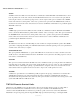
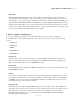
TW7000 SERIES HF TRANSCEIVER section 4 Broadband Antenna Configuration Diagrams The 3 diagrams shown below illustrate a few of the best ways to configure the ABB-series of broadband antennas. The drawings illustrate 3 basic installation configurations - a delta loop, a rectangle, and a diamond. Both the ABB100 and the ABB1000 can be installed in this fashion.
TW7000 SERIES HF TRANSCEIVER section 4 UV Resistant Nylon support wire ABB100AN – Rectangular Configuration Insulator ( on four corners) 48 ft (14.6m) 48 ft (14.6m) 116 ft (35.4m) 10 ft (3m) 10 ft (3m) ABB100A – Diamond Configuration 77 ft (23.5M) (all four sides) 56 ft (17m) Insulator Insulator Guy wire Guy wire 10 ft (3m) 147 ft (44.
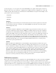
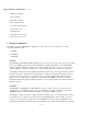
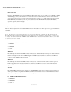
TW7000 SERIES HF TRANSCEIVER section 4 Accessory Wiring Diagrams Interconnect diagrams for connection of major accessory items to the TW7000 are shown on the following pages. These three diagrams illustrate the primary power, control, and RF cabling that is used to connect these accessory items to the transceiver.
TW7000 SERIES HF TRANSCEIVER section 4 Section 4–26
TW7000 SERIES HF TRANSCEIVER section 4 Section 4–27
TW7000 SERIES HF TRANSCEIVER section 4 Rack Equipment Configurations The following table shows the rack heights for various TW7000 equipment. Rack heights are given in “U” units, where one “U” unit is equal to 1.75 inches. Blank rack panels are also available to complete the rack if the equipment doesn’t use the full height. These panels are gray for the TW7000 equipment. They have part numbers RP1G through RP9G, with the digit indicating the rack height.