Operation Manual
Mopho Operation Manual Version 1.2 August 2009 Dave Smith Instruments 1590 Sylvaner Avenue Saint Helena, CA 94574-2340 USA ©2008-2009 Dave Smith Instruments www.DaveSmithInstruments.
Tested To Comply With FCC Standards FOR OFFICE USE This device complies with Part 15 of the FCC Rules. Operation is subject to the following two conditions: (1) This device may not cause harmful interference and (2) this device must accept any interference received, including interference that may cause undesired operation. This Class B digital apparatus meets all requirements of the Canadian Interference-Causing Equipment Regulations.
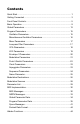
Contents Quick Start................................................................................................. 1 Getting Connected .................................................................................... 3 Front Panel Controls ................................................................................. 5 Basic Operation......................................................................................... 9 Global Parameters .........................................................
Quick Start Thanks for purchasing your Mopho synthesizer! Listen to the sounds, twiddle some knobs, have some fun! Please Register! Please go to www.davesmithinstruments.com and register your synth. If you purchased directly from us, there is no need to register—we already have your contact information. Powering Up So, plug in the power supply, connect (in stereo!!) to your mixer/sound system, and start playing! You can use the PUSH IT switch to trigger sounds without a keyboard.
read through the manual to discover all the little features that you might not notice at first. Don’t forget you get a free editor for Mac OS or Windows with your purchase. Download it from www.soundtower.com/mopho. I should mention that this manual does not include explanations of basic analog synthesizer functions. It assumes you already know what an oscillator is, how a low-pass filter affects the sound, what an ADSR envelope looks like, and so on.
Getting Connected Mopho has several inputs and outputs on its back panel. Power Input — Connect the power supply included with your Mopho. The power supply comes with different AC adaptor prongs that enable it to work almost anywhere in the world. If for whatever reason you need to use a different supply, it must match the specifications printed on the front panel. Note: The power supply label says “Evolver” on it; we use the same supply for the mono Evolvers, the Prophets, and Tetra.
4
Front Panel Controls Input Gain — Used to adjust the gain of AUDIO IN. For more about using Mopho to process external audio, see page 11. For low-level sources (like guitars), INPUT GAIN should be turned up. For line-level sources, it will usually be turned down. Turning it down does not turn it off, it just decreases the gain.
mode and displays the last parameter edited and its stored and edited values. See Program Parameters starting on page 15 for more information. Global mode is accessed by briefly holding down the PROGRAM MODE button. The Global menu is displayed. Use PROGRAM to change global parameters and the increment and decrement (+ and -) buttons to change the settings. See Global Parameters on page 13 for more information. To return to program mode from edit or global mode, simply press PROGRAM MODE.
Pitch — Controls the base frequency of the two oscillators. The relative interval between the two oscillators is maintained, even when the extremes are reached. Cutoff — Controls the filter cutoff. Resonance — Controls filter resonance. Note: The filter will only self oscillate when in 4-pole mode. See Lowpass Filter Parameters on page 17 for more information. Attack — Simultaneously adjusts the attack portion of all envelope generators: filter, amplifier, and Envelope 3.
Basic Operation In designing Mopho, the goal was to make a great sounding analog mono synth that was also affordable. Toward that end, we wanted to give players enough control over parameters to make it useful for performance, so we came up with a combination of “hard-wired” commonly used controls and user-assignable controls. Any of Mopho’s parameters can be edited in real time from the front panel controls. But we also recognize that may not be the quickest or easiest way to program sounds from scratch.
10
INPUT GAIN also affects the level of the feedback signal, so you’ll typically want to start with INPUT GAIN turned down. Several of the factory programs already have some level of feedback programmed in, as indicated by the letters “FB” following the name. To hear the effect of ExtIn Vol and INPUT GAIN, call up one of those programs and vary those parameters. Audio In Audio In can also be used to process an external audio source, to get access to the analog filter as a sound processor.
Global Parameters Mopho’s Global parameters affect all programs globally. Examples include MIDI channel and fine tune. To edit the Global parameters, hold down the PROGRAM MODE switch until Global Parameter is displayed. The PROGRAM knob changes the global parameter and the increment and decrement buttons change the value. Transpose: -12…+12 — Master Transpose control, 0 is centered. Steps in semitones. Fine Tune: -50…+50 — Master Fine Tune control; 0 centered. Steps in cents (50 cents = 1/2 semitone).
Audio Out: Stereo, Mono — Mopho defaults to stereo operation. When set to Mono, this parameter defeats all pan settings and modulation, effectively making each of the outputs a mono output. MIDI Out Select: Out, Thru — MIDI Out can be switched to MIDI Thru to daisychain multiple MIDI devices. Basic Patch — Press the WRITE button to load a basic patch into the edit buffer.
Program Parameters All Program parameters can be edited using any of the ASSIGNABLE PARAMETERS controls. To assign a parameter to a control, press the ASSIGN PARAMETERS button to light the LED, and then turn any of the knobs (1 through 4) to select a parameter. A full list of the parameters can be found on page 29. The selected parameter and value appear in the LCD display. The top line of the LCD displays the programmed value for reference; the bottom line displays the edited value.
Shape: see table — Selects the oscillator waveshape as follows: Display Osc Off Waveshape No output Sawtooth Sawtooth Triangle Triangle Saw-Tri Sawtooth — Triangle mix Pulse xx Pulse Wave, with pulse width ranging from minimum (0) to maximum (99). The pulse width will turn off at the two extremes — this allows some interesting modulation possibilities. A square wave will be at Pulse 50. Glide: 0…127 — Sets the oscillator glide (portamento) rate. Glide can be set independently for each oscillator.
allows subtle amounts of frequency drift. For larger amounts, use a random LFO or white noise mod. Pitch Wheel Range: 0…12 — Sets the bend range, in semitones, of the pitch wheel. The setting is the range in the positive or negative direction. For example, a setting of 7 lets you bend a note up or down by a fifth. Key Assign: see table — Determines how Mopho responds to keyed notes.
Resonance: 0…127 — Sets the Resonance level of the filter. At high settings the filter will self-oscillate in 4-pole mode. If the filter does not oscillate, switch to 4-pole mode. Keyboard Amount: 0…127 — Sets the amount of keyboard (MIDI note) to the filter cutoff. A setting of 64 will step the filter one semitone for each note, 32 would be half-semitones, and so on. Audio Mod: 0...127 — Controls the amount of audio from Oscillator 1 used to modulate the filter cutoff frequency.
Env Amount: 0…127 — Sets the amount of VCA envelope to the VCA level. Env Velocity: 0…127 — Sets the amount of keyboard velocity controlling the level of the VCA envelope. Delay: 0...127 — Sets a delay between the time the amplifier envelope is triggered and when the Attack portion actually begins. Attack: 0…127 — Sets the Attack time of the VCA ADSR envelope generator. Decay: 0…127 — Sets the Decay time. Sustain: 0…127 — Sets the Sustain level. Release: 0…127 — Sets the Release time.
3 Steps Sequence speed divided by 3 2 Steps Sequence speed divided by 2 1.5 Step 1 Step Sequence speed divided by 1.
Env Delay: 0…127 — Sets a delay between the time Envelope 3 is triggered and when the Attack portion actually begins. Env Attack: 0…127 — Sets the Attack time of Envelope 3. Env Decay: 0…127 — Sets the Decay time. Env Sustain: 0…127 — Sets the Sustain level. Env Release: 0…127 — Sets the Release time. Repeat: Off, On — When on, causes the delay, attack, decay, and sustain portions of Envelope 3 to loop for as long as the envelope is gated on.
Mod Wheel Destination — Selects the destination to which the mod wheel is routed. See Modulation Destinations on page 26 for a list of possible destinations. Press Amount: -127…+127 — Sets the maximum amount of modulation that can be applied from MIDI Channel Pressure (aftertouch). Press Destination — Selects the destination to which the Channel Pressure is routed. See Modulation Destinations on page 26 for a list of possible destinations.
Somewhat related, the Audio In setting will generate a gate from the Audio Input. When the signal gets above a certain level, the gate will go on. When it drops below that level, the gate will go off. Clock Parameters The sequencer and arpeggiator share the BPM and CLOCK DIVIDE settings. BPM: 30…250 — Sets the programmed tempo for the sequencer in BPM (beats per minute). Clock Divide: see table — Sets the note value for each sequence step relative to the BPM.
Mode: see table — Sets the order in which the arpeggiator plays notes. Display Up Arpeggiator mode Arpeggiated notes play in ascending order. Down Arpeggiated notes play in descending order. Up Down Assign Arpeggiated notes play in alternately ascending and descending order. Arpeggiated notes play in the order in which they were struck. On/Off: Off, On — Turns the arpeggiator on and off. Turning it on will turn off the Sequencer if it is on.
Seq Trigger: see table — Sets the triggering mode for the Gated Sequencer. Display Normal No Reset No Gate NoGateNR Key Step Audio In Trigger mode Sequence plays from the first step when a key is held, and resets to step 1 each time a new note is played. Each sequence step retriggers the envelopes. The same, but does not reset to step 1 on every note. The keyboard triggers the envelopes; the sequence steps do not. Same, but does not reset with subsequent notes.
Modulation Destinations Display Off Destination No destination selected Osc 1 Freq Oscillator 1 Frequency Osc 2 Freq Oscillator 2 Frequency OscAllFreq Oscillator 1 and 2 Frequency Osc Mix NoiseLevel Noise Level Osc1 PulsW Oscillator 1 Pulse Width Osc2 PulsW Oscillator 2 Pulse Width Osc All PW All Oscillators Pulse Width Low Pass Lowpass Filter Frequency Resonance Resonance Audio Mod Audio Mod Amount VCA Level VCA Amount Output Pan Stereo Pan Position LFO 1 Freq LFO 1 Frequency LF
Env3Releas Envelope 3 Release Rate EnvAll Rel All Envelope Release Rates Mod 1 Amt Modulator 1 Amount Mod 2 Amt Modulator 2 Amount Mod 3 Amt Modulator 3 Amount Mod 4 Amt Modulator 4 Amount AudioInVol Mixer Audio In Volume Sub Osc 1 Sub Oscillator 1 Level Sub Osc 2 Sub Oscillator 2 Level 27
Modulation Sources Display Off Source No source selected Sequence1 Sequence 1 Sequence2 Sequence 2 Sequence3 Sequence 3 Sequence4 Sequence 4 LFO 1 LFO 1 LFO 2 LFO 2 LFO 3 LFO 3 LFO 4 LFO 4 Filt Env1 Filter Envelope VCA Env 2 Amp (VCA) Envelope Envelope3 Envelope 3 PitchBend Pitch Bend Mod Wheel Mod Wheel Pressure Pressure (Aftertouch) MidBreath MIDI — Breath Controller Midi Foot MIDI — Foot Controller Midi Exp MIDI — Expression Velocity Keyboard Note Velocity KeyNumber
Parameter List Osc 1 Frequency Osc 1 Fine Freq Oscillator 1 Shape Oscillator 1 Glide Osc 1 Key Track Sub Osc 1 Level Osc 2 Frequency Osc 2 Fine Freq Oscillator 2 Shape Oscillator 2 Glide Osc 2 Key Track Sub Osc 2 Level Osc Hard Sync Glide Mode Oscillator Slop Pitch Wheel Range Key Assign Oscillator Mix Noise Level Ext In Volume Filter Cutoff Freq Filter Resonance Filter Keyboard Amt Filter Audio Mod Filter Config/Mode Filter Env Amount Filter Env Velocity Filter Env Delay Filter Env Attack Filter Env Decay
MIDI Implementation Mopho receives MIDI data according to the mode controls under GLOBAL. In addition, there is interaction between some of the Program parameters that determine the overall response of Mopho to MIDI data. Following are the Global parameters that affect response to MIDI: MIDI Channel: ALL, 1…16 — Selects the MIDI channel to send and receive data, 1 to 16. All receives on any channel.
Received Channel Messages Status 1000 nnnn 1001 nnnn 1010 nnnn 1011 nnnn Second 0kkkkkkk 0kkkkkkk 0kkkkkkk 0vvvvvvv 1100 nnnn 0ppppppp 1101 nnnn 1110 nnnn 0vvvvvvv 0vvvvvvv Notes: 0kkkkkkk nnnn Third 0vvvvvvv 0vvvvvvv 0vvvvvvv 0vvvvvvv 0vvvvvvv Description Note Off. Velocity is ignored Note On.
Transmitted Controller Messages Status 1011 nnnn 1011 nnnn Second 0000 0111 0010 0000 Third 0vvvvvvv 0vvvvvvv Description Volume knob Bank Select — 0 to 2 See sections below for additional Continuous Controller (CC) and Nonregistered Parameter Number (NRPN) messages transmitted. Additional Continuous Controllers (CCs) Transmitted/Received The following table details how CCs are mapped onto Mopho’s controls.
NRPN Messages The Non-Registered Parameter Number (NRPN) MIDI messages are used to transmit and receive both global and program parameters. They are transmitted when MIDI Parameter Send is set to NRPN in Global, and received when MIDI Parameter Receive is set to either NRPN or All in Global. The messages are handled in standard MIDI format using the NRPN CC commands in running status byte format.
Received NRPN Messages Status Second Third Description 1011 nnnn 0110 0011 0vvvvvvv NRPN parameter number MSB CC 1011 nnnn 0110 0010 0vvvvvvv NRPN parameter number LSB CC 1011 nnnn 0000 0110 0vvvvvvv NRPN parameter value MSB CC 1011 nnnn 0010 0110 0vvvvvvv NRPN parameter value LSB CC 1011 nnnn 0110 0000 0xxxxxxx NRPN parameter value Increment 1011 nnnn 0110 0001 0xxxxxxx NRPN parameter value Decrement 1011 nnnn 0010 0101 0111111 RPN parameter number MSB CC — Reset NRPN parame
8 405 0-1 Audio Out: 0 Stereo 1 Mono 9 406 0-1 MIDI Out Select: 0 MIDI Out 1 MIDI Thru Program Parameter Data The following table lists Mopho’s voice parameters. The parameter number in the program and edit buffer dumps are different than the NRPN numbers as seen; this was to maintain NRPN compatibility with the Prophet ’08 as much as possible.
36 16 96 0-5 Key Assign Mode: Low note priority Low note priority with re-trigger High note priority High note priority with re-trigger Last note hit priority Last note hit priority with re-trigger 17 18 19 13 14 116 0 - 127 0 - 127 0 - 127 Oscillator 1 - 2 Mix Noise Level External Audio Input Level 20 21 22 23 24 25 26 27 28 29 30 31 15 16 17 18 19 20 21 22 23 24 25 26 0 - 164 0 - 127 0 - 127 0 - 127 0-1 0 - 254 0 - 127 0 - 127 0 - 127 0 - 127 0 - 127 0 - 127 Filter Frequency, steps in semitone
42 38 0-4 43 44 39 40 0 - 127 0 - 46 45 46 47 48 49 41 42 43 44 45 0-1 0 - 166 0-4 0 - 127 0 - 46 50 51 52 53 54 46 47 48 49 50 0-1 0 - 166 0-4 0 - 127 0 - 46 55 56 57 58 59 51 52 53 54 55 0-1 0 - 166 0-4 0 - 127 0 - 46 60 56 0-1 61 57 0 - 46 62 63 64 65 66 67 68 69 58 59 60 61 62 63 64 98 0 - 254 0 - 127 0 - 127 0 - 127 0 - 127 0 - 127 0 - 127 0-1 70 71 72 65 66 67 0 - 22 0 - 254 0 - 46 73 74 68 69 0 - 22 0 - 254 165 Eight cycles per step 166 Sixteen cycles per step LFO 1 Shap
38 75 70 0 - 46 Mod 2 Destination; See Modulation Destination list below Mod 3 Source; See Modulation Source list below Mod3 Amount; -127 to +127 Mod 3 Destination; See Modulation Destination list below Mod 4 Source; See Modulation Source list below Mod 4 Amount; -127 to +127 Mod 4 Destination; See Modulation Destination list below 76 77 78 71 72 73 0 - 22 0 - 254 0 - 46 79 80 81 74 75 76 0 - 22 0 - 254 0 - 46 82 83 81 82 0 - 254 0 - 46 84 85 86 87 88 89 90 91 83 84 85 86 87 88 89 90 0 - 254
97 97 0-3 98 99 100 94 0-1 0-5 100 101 101 77 0-1 0 - 46 102 78 0 - 46 103 79 0 - 46 104 80 0 - 46 105 106 107 108 109 - 119 120 - 135 105 106 107 108 0 - 183 0 - 183 0 - 183 0 - 183 120 - 135 0 - 127 136 - 151 136 - 151 0 - 126 152 - 167 152 - 167 0 - 126 168 - 183 168 - 183 0 - 126 184 - 199 200-255 184 - 199 32 - 127 Arpeggiator Mode: 0 Up 1 Down 2 Up/Down 3 Assign Arpeggiator; Off/On Sequencer Trigger: 0 Normal 1 Normal, no reset 2 No gate 3 No gate/no reset 4 Key Step
The following tables list the values used with the program parameters to specify modulation destinations and sources.
Mod 1 Amt Mod 2 Amt Mod 3 Amt Mod 4 Amt External Audio In Level Sub Osc 1 Level Sub Osc 2 Level Mod Sources Off Sequence Track 1 Sequence Track 2 Sequence Track 3 Sequence Track 4 LFO 1 LFO 2 LFO 3 LFO 4 Filter Envelope Amp Envelope Envelope 3 Pitch Bend Mod Wheel Pressure MIDI Breath MIDI Foot MIDI Expression Velocity Note Number Noise Audio In Envelope Follower Audio In Peak Hold 40 41 42 43 44 45 46 Value 0 1 2 3 4 5 6 7 8 9 10 11 12 13 14 15 16 17 18 19 20 21 22 Sysex Messages Universal System Exclusi
Mopho responds with: Status 1111 0000 0111 1110 0vvv vvvv 0000 0110 0000 0010 0000 0001 0010 0101 0000 0001 0000 0000 0000 0000 0jjj nnnn 0000 0000 0000 0000 1111 0111 Description System Exclusive (SysEx) Non-realtime message If MIDI Channel = ALL, 0vvvvvvv = 0111 1111. Otherwise 0vvvvvvv = Channel Number 0 - 15.
Request Global Parameter Dump Status Description 1111 0000 System Exclusive (SysEx) 0000 0001 DSI ID 0010 0101 Mopho ID 0000 1110 Request Global Parameter Transmit 1111 0111 End of Exclusive (EOX) Mopho will respond by sending out the current values of Global Parameters in the format described below in Global Parameters Data Dump.
Global Parameters Data Dump Status Description 1111 0000 System Exclusive (SysEx) 0000 0001 DSI ID 0010 0101 Mopho ID 0000 1111 Main Parameter Data 0vvv vvvv 20 nibbles (LS then MS) for 10 Global parameters. Global Parameters are listed starting on page 34. 1111 0111 End of Exclusive (EOX) Note: The Global Parameters Data Dump is not recognized when received; it is only transmitted when requested. NRPN messages are used to change Globals.
Dave Smith Instruments 1210 Cabrillo Hwy N Half Moon Bay, CA 94019-1449 USA www.DaveSmithInstruments.