ChloroMatic ® Salt Water Pool System Installation & Operating Instructions Models MCS16C MCS16CTP MCS24C MCS24CTP MCS36C MCS36CP MCS40C MCS50C MC16C MC20C MC30C Please pass these instructions on to the operator of this equipment. Email: sales@davey.com.au davey.com.
ChloroMatic ® Salt Water Pool System Congratulations! You are now the proud owner of the renowned ChloroMatic® Salt Water Chlorinator.Please read all information in this manual carefully before installing or operating your ChloroMatic® Salt Water Pool Chlorinator. Table of Contents Packing List................................................................................................................................................................. 2 Important Notice.................................
IMPORTANT NOTICE FACTORS THAT WILL IMPROVE THE PERFORMANCE AND LIFE OF YOUR SALT WATER CHLORINATOR PLEASE READ THIS BEFORE OPERATING YOUR CHLORINATOR POOL BUILDERS: Please cover this information with your customer during the new pool “Hand over Session” Salt Water Chlorinators are a valuable piece of pool sanitising equipment and must be cared for to get the best performance and life span from it. There are THREE main factors that will damage your chlorinator and reduce the life of the product.
Note: The Chlorinator is not intended for use by young children or infirm persons without supervision. Please ensure that young children are supervised to ensure that they do not play with the Chlorinator. Power connections and wiring must be carried out by an authorised electrician. INSTALLATION INSTRUCTIONS FOR CHLOROMATIC® (ESR and ESC) Note: For ESCpH models, please read all instructions then refer to page 15-17 for more information.
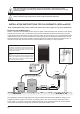
CONNECTING THE ELECTROLYTIC CELL TO THE POWER SUPPLY: The Power Supply is fitted with a flexible lead terminated with brass connectors. These must be correctly fitted to the connections on the inside of the Cell Head. To prevent incorrect connection the fittings have been colour coded. ESR Black to Black & White to White ESC / ESCpH Either Black Terminal The Blue Gas Sensor connector should be pushed onto the thread of the small bolt.
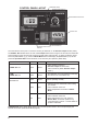
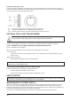
CONTROL PANEL LAYOUT OPERATION LED’S WINTER MODE SWITCH SANITISER OUTPUT DIAL TIME CLOCK 6 AM SELECTOR SWITCH OPTIONAL POOL LIGHT SWITCH Once the salt level in the pool is correct the unit may be switched on. Set Sanitiser Output to Max (100%). The Stand - by indicator will be On and no Cell Output will be seen for approx 30 seconds, this allows the pump and filter to prime and the Cell Housing to fill with water.
ChloroMatic® MODEL ESR, ESC and ESCpH SERIES FEATURES: STAND- BY: The Stand - By indicator will be On when the Unit is preparing to produce sanitiser. This will be either during the systems initial start up or when the Cell has been turned Off during the filtration cycle. FLOW: If there is a problem with water flow or gas is detected in the Cell Housing the fIow indicator will be On. When this occurs the pump or pipes should be inspected for damage and the Flow Sensor connection checked.
There are other factors that can cause the Unit not to work correctly: 1. Heavy Rain - can cause very diluted pool water to pass over the Cell due to surface skimming. 2. Scaled Cell - a scaled Cell will not draw as much electrical current as a clean Cell when first started. 3. Cold Water - cold pool water reduces the ability of a Cell to carry electrical current. (Refer Winter Mode below). 4. Failing Cell - as the Cell ages there will come a time when the electrical current draw will drop.
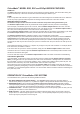
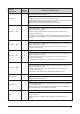
Function Description Selector Switch Position Functions and Instructions Set the current time on the digital clock. Set Clock 1 Select the Set Clock position on the selector switch to enable the time of day to be input. A number ‘1’ will appear at the left of the screen. (a) The display will flash on and off as long as the selector switch remains at this position. Use the up ▲ and down ▼ buttons to reach the desired times. Hold the buttons down for fast increments.
(2) Models with Analogue Timer If your Power Supply is fitted with an analogue time clock the operating time(s) can be easily set by pushing the small pins forward or backwards to the desired operating time(s). The unit comes pre-set for 8 hours operation per day. The ON-OFF-AUTO switch functions as follows: On Off Auto- Over-rides automatic time clock, Filtration System switched on. Over-rides automatic time clock, Filtration System switched off.
MAINTENANCE OF ELECTROLYTIC CELL: The cell is composed of precious materials, and although proper maintenance can prolong its life to the maximum, eventually the process of electrolysis will wear away its delicate coating, at which time it gradually ceases to produce chlorine. Mineral salts and calcium (scale) are deposited on the outer and the inner plate as electrolysis takes place. This build up – will interfere with the flow of electrical current in the Cell and thus lowers sanitiser production.
METHOD 2 As an alternative, an approved commercial Cell cleaning solution can be used a number of times effectively. WARNING: Follow safety instructions provided with the Hydrochloric Acid or cleaning solution. When handling Hydrochloric Acid, the use of eye protection, mask and gloves are highly recommended. Extreme caution should be taken whenever handling Hydrochloric Acid or Cell Cleaning Solution. SAFETY DEVICE: Hydrogen Gas is a by – product of the chlorine producing process.
Salt is NOT used up in the process of producing chlorine or by evaporation. Salt is only lost through back washing, splash - out, overflow or by leakage from the pool or plumbing. Winter rains can dilute the salt solution in your pool; therefore salt levels should be checked during this season. In colder water, the ChloroMatic should be set to Winter Mode. (Refer Winter Mode page 8). Low salt levels will destroy the coating on the Anode plates and will void all Warranty.
NOTE: The appropriate chlorinator size for your pool is dependent on the local climate and the bather load of the pool. Please note that chlorinator cell life can be increased with shorter running times during winter and lower output settings. Davey recommends that a chlorinator is run for between 6 - 8 hours a day during summer, and 4 hours during winter.
IMPORTANT NOTES: 1. The ChloroMatic guarantee does not apply to commercial or semi-commercial installations, i.e. where the system runs more than an average of 8 hours per day over the year. Guarantee on commercial and semi-commercial installations is 12 months only on both power supply and cells. 2. ALWAYS INSIST ON GENUINE CHLOROMATIC REPLACEMENT PARTS. If it is necessary to replace the Electrolytic Cell, beware of “look alikes”.
SIMPLE DESCRIPTION OF OPERATION The pH control has been designed to provide an acid feed in proportion to the difference between the actual pH and the pH set point. The control also operates on a cycle to allow the acid being fed to mix with the pool water. The cycle is approximately five minutes duration. If the pH is 0.3pH or more above the set pH at the start of a cycle the acid dosing pump will operate continuously until the pH falls below the set point plus 0.3pH.
4. Switch the pH Control to SET and adjust to the desired pH if necessary. NOTE: for concrete pools it is possible that a pH set point of around 7.4 or below will lead to high acid consumption and frequent additions of buffer. To reduce this effect a set point of 7.7 may be more economical. 5. Switch pH Control to RUN and allow unit to operate. 6. Retest pool pH with test kit over the next few days to fine tune control if necessary 7.
Notes & Service History: 18
Davey® Repair or Replacement Guarantee In the unlikely event in Australia or New Zealand that this Davey product develops any malfunction within warranty periods beginning from the date of original purchase due to faulty materials or manufacture, Davey will at our option repair or replace it for you free of charge, subject to the conditions below.