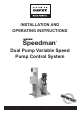
INSTALLATION AND OPERATING INSTRUCTIONS Speedman ® Dual Pump Variable Speed Pump Control System Please pass these instructions on to the operator of this equipment.
Safety Warnings Warning: Always disconnect the pump and controller from the electrical supply before maintenance or repairs. IMPORTANT: DO NOT USE petroleum based fluids or solvents (e.g. oils, kerosene, turpentine, thinners, etc) on the plastic or seal components. WARNING: When servicing or attending the pump or controller, always ensure power is switched off and lead unplugged. Electrical connections should be serviced only by qualified persons.
CONTENTS INTRODUCTION 2 QUICKSTART 4 CANCELLING AUDIBLE BEEPER 6 PUMP CONTROL PANEL 7 MOVING AROUND & EDITING THE MENU ITEMS 8 MENUS 9 SYSTEM DISPLAY MENUS 18 FAULT HISTORY 18 PUMP DATA LOG 19 ACCESS CODE 21 SETTINGS 22 TUNING 26 TIMING 28 CONFIGURE 30 PUMP DEFINITIONS 35 JOCKEY PUMP 35 OUTPUTS 38 INPUTS 40 ANALOGUE INPUTS 45 PIPE FILL MODE 46 RESTORE OPTIONS 47 TIME OF DAY SET POINTS 47 PID CONTROL 51 PRESSURE TANK REQUIREMENTS 53 VSD SETTINGS 53 SPECIFICAT
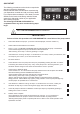
Quickstart The following procedures are the minimum required to start and operate the Speedman. Please read the entire manual before commissioning your Speedman controller and call your Davey dealer if you require further assistance. Your dealer’s contact details can be found via the Davey website. Please quote the 4 digit serial number of your application when making enquiries. . The following ROTATION CHECK MUST be completed before any other commissioning steps begin.
Adjust Set Point (Operating Pressure of your system) 1. 2. 3. 4. 5. 6. 7. 8. Press the DOWN key until the Message “Access Code” is displayed. Press the ENTER (*) key. The top line of the display will start flashing. Then press the UP key until the number 21 appears in the lower part of the screen. Press the ENTER (*) key again and the top line of the display will stop flashing. The access code is now entered. Press the DOWN key once more. A menu named SETTINGS will appear.
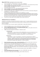
System Operation The operating constraints for the system are detailed below. HIGH PRESSURE SHUTDOWN HIGH PRESSURE LIMIT SET POINT PRESSURE SYSTEM CUT IN PRESSURE LOW PRESSURE SHUT DOWN When the system pressure drops below the SYSTEM CUT IN pressure setting, the Speedman will start the VSD to run the first pump and increases in speed until the SET POINT PRESSURE is reached. If one pump cannot satisfy the pressure requirement another pump will start.
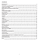
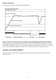
PUMP CONTROL PANEL The Speedman Control Panel allows the operator to edit settings and values in each menu. Two line LCD Display Pump RUN Indicator Pump Enable Indicator Pump Enable Button To edit values and settings within menus Press the ENTER (*) key when the desired menu is displayed. The top line will flash if the menu can be edited (some menus may be locked and unavailable). Use the UP and DOWN buttons to change the selection, then press ENTER (*) again to confirm the change.
MOVING AROUND & EDITING THE MENU ITEMS To move between the Main Menu screens press the UP or DOWN key Once the required Menu is selected press the ENTER (*) Key to enter the specific menu. To edit a value, a valid Access Code needs to be entered. If the Access Code is not inserted correctly the system will inhibit menu selection and pump select keys. To edit a value press the ENTER (*) key and then the UP or DOWN key until the desired value is displayed.
MENUS Navigating the through the menus is very simple. • Press UP or Down button to navigate the Main menu set to find the appropriate sub menu. • Press the * to enter any Sub menu. • Then press down to find the required sub menu item. • When the required sub menu is selected, press the * button, the display will flash, then press the UP or DOWN button to change the value. • Press * again to lock in the data. • Pressing the UP or DOWN button continuously will eventually return to the main menu.
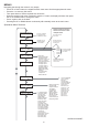
CONFIGURE Press * For Menu PUMP DEFINITION Press * For Menu JOCKEY PUMP Press * For Menu OUTPUTS Press * For Menu INPUTS Press * For Menu Pumps 1 to 2 (Duty/Standby Backup or Jockey) Jockey Pump On/Off Use Main Setpoints JP Cut In Pressure JP Set Point JP Cut Out Pressure JP Flow Rate Digital Output 1 to 2 JP Response Rate Analogue Output 1 JP Acceleration Analogue Output 2 JP Standby Test JP Standby Boost JP Standby FlowMin Program Input 1 to 8 JP Run On Time JP Restart Delay Analogue Input 1 JP Min
The Speedman controller has menus to allow the system to be tuned. These menus are listed below and explained in detail later in this manual.
Sub Menu Units Range Defaults *1 Low Press Shutdown % or Units 50.
Sub Menu Units Range Defaults *6 *5 Minimum Frequency Shutoff Head Response Rate (P Acceleration Hi Press Restarts Standby Boost Standby Flow Min Fallback FlowMin % Unitless % %/second number % of Setpoint /Sec Unitless /Sec 45.0 1924 2.0 20 Off 20 200 200 *2 Error Correction (I seconds *2 Overshoot Elimination (D % *4 RR(P) EC(I) OE(D) Numbers x 3 0.0 - 100.0 0 - 9999 0.1 - 100.0 1 - 100 Off, 1 - 250 10 - 250 0 - 9999 1 - 9999 Off, 0.1 - 100.0 Off, 0.1 - 50.
Sub Menu Units Range Defaults Lo Press Delay seconds 120 Hi Press Delay seconds *1 *4 In Delay Timer Out Delay Timer Restart Delay Standby Test Time Fallback Delay seconds seconds seconds seconds seconds *2 Boost Hold Time seconds * * * * *3 *3 Pump Fault Timer No Flow Delay I/P Delay Timer Press Trip Low Delay Press Trip High Delay Flow Trip Low Delay Flow Trip High Delay Stop Time (24hr) Start Time (24hr) seconds seconds seconds seconds seconds seconds seconds HH:MM HH:MM Off, 0 - 250 Of
Sub Menu Units Range Defaults Operating Mode selection Pressure Level Mode selection Number of pumps Min Freq Mode Press Decimal Flow Decimal Transducer Zero Adjust Pressure Averaging Flow Meter Zero Adjust Flow Backup Pres Zero Adjust Backup Pr Scale An output 2 JP Fallback Standby Test Fallback Test Set Time/Date Operating System Friction Loss Calc Access Code Serial Comms Modbus Address Flow Sensing Manual Run number selection number number Unitless Unitless number /Sec /Sec Unitless Unitless n
PIPE FILL * * * * * * Sub Menu Units Range Defaults Pipe Fill Mode Jump Ramp Time Jump Final Speed Pipe Fill Time Pipe Empty Pressure Pipe Empty Time selection seconds % seconds Unitless seconds On, Off Off, 1 - 999 0-100% 5 - 999 0 - 9999 0 - 999 Off Off 50 100 200 200 These menus are related to other settings. They are not visible unless related settings are enabled.
Sub Menu Units Range Defaults Digital Output 1 selection Any of the following can be selected on any output and used multiple times Jockey Pump Run Digital Output 2 selection Any Pump Shutdown Analogue Output 1 Analogue Output 2 Shutdown Fault, Lo Press Fault, Hi Press Fault, Any Alarm, Pump 1 - 6 Run, Pump 1 - 6 Fault, System Paused, Any Pump Shutdown, Any Pump Running, No Flow Shutdown, VSD Fault, Pressure Trip 1 - 2, Alternate Trip, Flow Trip, Jockey PumpRun, Aux Output 1 - 3, Set Point Outpu
Sub Menu Units Range Defaults Main VFD, Separate VFD, DOL 0 - 9999 0 - 9999 0 - 9999 0 - 9999 0.1 - 100.0 1 - 100 Off,Boost,Flow Switch, Flow Rate 5 - 250 0 - 250 0 - 999 0 - 999 Yes, No 0.0 - 100.0 Off, 0.1- 100.0 Off, 0.01 - 50.
SYSTEM DISPLAY MENUS Set-Pr Actual -Pr Flow-Rate VFD-Sp number number 0 - 9999 0 - 9999 0 - 9999 0 - 100 display display Set Point and Actual Pressure The Actual Pressure is measured in the discharge pipeline of the system by the pressure transducer and is displayed on the Speedman Pressure status screen (Actual-Pr), next to the Pressure Set Point (Set-Pr). Set-PR XXXX Actual-PR XXXX If the jockey pump is running on the main VSD, then the jockey pump set point will appear.
NOTE: The FAULT HISTORY menu is cleared when the system is first powered up. If there is a problem with the clock or the clock hasn’t been initialised correctly then “RTC ERROR” will appear along with the fault. See “Set Time and Date” in the CONFIGURE menu for more details. “Pump 1 - 2 Shutdown” signifies that the corresponding “Pump protect 1-6” input has been activated for the period of the input delay time. A HIGH TEMPERATURE fault is recorded when the temperature rises above 60 degrees C.
Average Pressure The Average Pressure calculated over the period since the last reset. To reset press ENTER. Average Pressure XXXX Highest Pressure The Highest Pressure is the highest pressure point reached since the last reset of this log. To reset press ENTER. Highest Pressure XXXX Hours Run Pump 1-2 Each pump has an hour run meter. The hour log displays the operation time for each pump in both AUTOMATIC and MANUAL modes. To reset the time press ENTER.
Digital Input State M (Main Inputs) Displayed is the state of the Digital inputs X = energised - = de-energised See INPUTS for configurable options for this item. Digital Input M X--X---- Highest Pressure Displayed is the state of the Digital outputs X = energized - = de-energized See OUTPUTS for configurable options for this item. Digital Output X- PID Error Displayed is the calculated error between the Set Point and actual pressure. PID Error XXX.
SETTINGS Low Pressure Shutdown Cut In Pressure Set Point High Pressure Limit High Pressure Shutdown Pump Flow Rate Friction Loss Set Point 2 Set Point 3 Set Point 4 Set Point 5 Set Point 6 Set Point 7 Set Point 8 Pressure Trip 1 Low Pressure Trip 1 High Pressure Trip 2 Low Pressure Trip 2 High Flow Trip Low Flow Trip High Units or % % of Setpoint Unitless % of Setpoint 0.0% Cut In Pressure Low Pressure Shutdown to 99.9% 0 - 9999 100.1% to High Pressure Shutdown 50.0% 75.0% 300 150.
High Pressure Limit The High Pressure Limit is the pressure point that stops pumps if the pressure rises above this limit. Once the pressure rises above this figure the fixed speed pumps will HiPress Limit shut down and the VSD rapidly decelerates. If the system pressure falls to below the XXX.X % High Pressure Limit the Speedman will restart and function normally. This setting is limited to a value that is lower than the High Pressure Shutdown and higher than the highest Set Point.
Friction Loss Friction loss is the figure that is added to the Set Point to compensate for Friction in a Friction Loss pipeline. The setting increases the Set Point Pressure based on the calculated flow XXX rate. The increase in Set Point is proportional to the calculated flow rate. The input figure is the total additional pressure required when all of the nominated pumps are operating. Linear Friction Loss Exponential Friction Loss NB.
Pressure Trip 1 High The High Trip point has a matching low Trip point. If a single trip point is required, set the High and Low trip points to the same value. Note: The settings of Trip high must be greater than or equal to Trip low. The system does not allow settings to be selected outside this range. Press Trip 1 Hi XXXX The “Pressure Trip 1 Low” and “Pressure Trip 1 High” screens will only appear if an output is set to “Pressure Trip 1” within the OUTPUTS menu.
TUNING Minimum Frequency Shutoff Head Response Rate Acceleration High Press Restarts Standby Boost Standby Flow Min Error Correction (I Overshoot Elimination (D RP(P) EC(I) OE(D % Unitless % %/second number % of Setpoint /Sec seconds % number 0.0 - 100.0 0 - 9999 0.1 - 100.0 1 - 100 Off, 1 - 250 10 - 250 0 - 9999 Off, 0.1 - 100.0 Off, 0.1 - 50.00 -1000, 1000 45.0 1924 2.0 20 Off 20 200 3.0 15.
Standby Boost / Standby Flow Min The Speedman uses one of three methods to determine if there is “no flow”. Standby Boost The options detailed below are selected via the “Standby Test” screen, which XXX is in the CONFIGURE menu. Each test is only carried out if there is 1 pump running, not at maximum speed and the system pressure is at or above the Set Point.
RR(P) Proportional Output Displays the proportional component within the PID equation. Proportional is another name for “Response Rate” EC(I) Error Correction Displays the error correction component within the PID equation. RR(P) EC(I) OE(D) XXX XXX XXX OE(D) Overshoot Elimination Displays the overshoot elimination component within the PID equation. These three “Output” display values help in the tuning of the Speedman. Each has a range of -1000 to 1000. See PID Control for more information.
Out Delay Timer When the pumps are called to shut down, a delay can be set using the “OUT DELAY TIMER”. **CAUTION** Take care in setting this timer as the increase in pressure due to this delay can cause pressure spikes. Out Delay Timer XXX Seconds Restart Delay When the system pressure drops below the Cut In Pressure the Speedman restart will be delayed by the RESTART DELAY.
Flow Trip High Delay Delays the deactivation of the relevant Speedman Output relay if programmed for Flow Trip. This delay timer is relevant for the High Flow Trip setting. Flow Trip Hi Dly XXX Seconds The screens “Flow Trip Low Delay” and “Flow Trip High Delay” are only visible if an output is set as “flow trip” in the OUTPUTS menu. Stop Time (24hr) & Start Time (24hr) The “Stop Time” and “Start Time” option allows a period of time to be set where the system will be paused. For Example: 1.
Level Mode Level Mode selects whether the Speedman is associated with a “Tank Filling” or “Tank Emptying” application and the level sensing set up. • • • • Level Mode Std An: Tank Fill Std An:Tank Fill – Tank Filling with a sensor that increases output signal as the tank fills. Std An:Tank Empty – Tank Emptying with a sensor that decreases output signal as the tank empties. Rev An: Tank Fill – Tank Filling with a sensor that decreases output signal as the tank fills.
Manual Zero (Primary Transducer) Press ENTER (*) and then the DOWN key to decrease the dispalyed value to ZERO. If “Value Too Low” appears, increase the value slowly by pressing the UP key until a zero value is obtained. *NOTE* The value does not change with each press of the UP/DOWN key. Press and hold the UP/DOWN key for rapid change and single press for small change. When ZERO is displayed press ENTER (*) to finish the operation. Reconnect pressure tube before re-enabling pumps.
Adjust Flow OR Adjust Backup Pr (Backup Transducer) Flow The calibration of the analogue sensors is achieved by adjusting the Speedman Flow Meter reading to match the reading from the system Flow Meter. Adjust Flow XXXXX /min Backup If the Analogue input is configured to be a backup pressure transducer then this Adjust Backup Pr display will be displayed instead of Flow. When the backup transducer is selected XXXX it will automatically swap between transducers should one transducer become out of range.
Friction Loss Calculator There are two methods of calculating the pressure loss. • • Friction Loss Linear Linear progression. Exponential extrapolation. Friction loss is the figure that is added to the Set Point to compensate for Friction in a pipeline. The result of this setting is to increase the Set Point Pressure based on the flow rate calculated. The input figure is the total additional pressure required when all of the nominated pumps are operating.
Flow Type The “Flow Type” setting allows the user to select how the flow rate is determined. Options are Calculated, Scaled AnInp2 or Digital Pulse. • • • Flow Type Calculated “Calculated” uses the flow rate setting “Pump Flow Rate” in the settings menus to calculate the current Flow Rate. “Scaled AnInp2” uses an analogue sensor (ether current-loop or variable voltage ) to determine the current Flow Rate. Digital Pulse uses a compatible digital output flow meter to determine the current Flow Rate.
The Jockey pump is typically a smaller auxiliary pump that is outside the flow range of the main pumps. The jockey pump will turn on when there are no main pumps running and the pressure is below Jockey “Cut-In” Pressure. The Jockey pump can be set up to “run-on” after the main pumps start but it will eventually be turned off. Once the main pump/s are running, they will then meet the increased demand.
JP Acceleration The acceleration of the VSD can be limited by this figure. It is designed to brake the PID control. It is used where the Acceleration needs to be dampened. The figure is input in %/second. JP Acceleration XXX %/Second JP Standby Test This option allows the Jockey Pump a number of different modes to determine if the system should be placed in standby mode. JP Test Off- Standby test is disabled therefore the system will always run unless controlled Boost by an external signal.
JP Error Correction (Integral Time) The error correction is the time it will take to convert a constant error of 1% to a 1% change on the output. This is useful when trying to close the gap on small errors that can not be eliminated through the use of the response rate alone. This value is specific to when the jockey pump is running on the VSD. JP ErrorCorr’t (1) XX.X Seconds It is expressed as a percentage ranging from OFF, 0.1 - 100.0. OFF will disable this part of the PID equation.
Digital Output Options No 1 2 3 4 5 6 7 8 9 10 11 12 13 14 15 16 17 18 19 20 21 22 23 24 25 26 27 28 29 Option Shutdown Fault Low Pressure Fault High Pressure Fault Any Alarm Pump 1 Run Pump 2 Run Pump 1 Fault Pump 2 Fault System Paused Any Pump Shutdown Any Pump Running No Flow Shutdown VFD Fault Pressure Trip 1 Pressure Trip 2 Alternate Trip Flow trip Jockey Pump Run Aux Output 1 Aux Output 2 Aux Output 3 SP 1 Output SP 2 Output SP 3 Output SP 4 Output SP 5 Output SP 6 Output SP 7 Output SP 8 Output Del
• Any Pump Running Any pump running will activate the relay. • No Flow Shutdown The No Flow Shutdown action is active. • VSD Fault Output is on when the VSD is being tested or the VSD has shutdown. • Pressure Trip 1 When the system pressure reaches the nominated Pressure Trip 1 Low and High, this relay will energise or de-energise. See Pressure Trip in SETTINGS.
There are 8 main inputs with the Speedman that control external sensing functions. All inputs are programmable to suit various applications. They all require VOLTAGE FREE contacts and as such should NOT HAVE ANY VOLTAGE APPLIED. • All inputs operate on a CLOSED CONTACT for activation. This contact needs to be made between the input common and the relevant input. There are three terminals for the input Common to allow for multiple connections.
Set Point 2-8 Closing of the contact to either of these inputs will activate the alternate set points 2 to 8. If two inputs are activated at the same time, then the Set Point with the highest number will be the selected option. Eg If Set Points 2 and 6 are activated Set Point 6 pressure setting will be used. The Set-Pr will also change on the main display. Soft Pause An external sensor can be used to PAUSE the system.
Pump 1 and 2 Manual Run Activation of this input will instantly start the relevant pump. All automatic control of the pump is ceased at this stage. This action can cause an alarm or shutdown condition. (See Manual operation) Fire Mode FIRE MODE directs the Speedman to ignore all shutdown alarms/faults and the pumps will continue under all conditions.
No Flow If the system detects that there should be flow but there is a No Flow signal from an Low Flow Detected external flow switch, the Speedman will display the message “Low Flow Detected”. XXXXX Once system detects a closed contact on this input the Speedman will time out and shut down. This is optional and requires a flow switch to feedback into the No Flow Input and will only operate if there is at least 1 pump selected to AUTO.
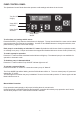
ANALOGUE INPUTS The standard transducer fitted to the Speedman is rated to 25Bar External Analogue Input The analogue terminals are located on the left hand side of the PCB near the top. The use of 4 – 20mA and 0-10V transducers require the slide switches to be placed to match the input. This allows the system to read the correct input from the transducers. Volts = 0-500mVDC,0-5VDC,0-10VDC etc mA= 0-20mA,4-20mA etc 4-20 mA is a standard analogue signal from a pressure transducer.
PIPE FILL MODE Pipe Fill Mode Jump Ramp Time Jump Final Speed Pipe Fill Time Pipe Empty Pressure Pipe Empty Time selection seconds % seconds unitless seconds On, Off Off, 1 - 999 0-100% 5 - 999 0 - 9999 0 - 999 Off Off 50 100 200 200 When a system has been idle for a period of time there may be loss of water in the system and a need to start the pumps slowly to reduce the possibility of Water Hammer. The Pipe Fill Control will override the SET POINT control in these circumstances.
RESTORE OPTIONS Create Backup Restore Backup *operation* *operation* The Speedman can backup settings. A backup can be created at any time via the “Create Backup” option in the “Restore Options” menu. Create Backup A backup is created and stored on the system. This will over write any previously stored backup. Only 1 backup set of data is possible. Create Backup Press * to Backup Restore Backup The backup is restored on the system. This item will be present only if a valid backup is available.
Pump Protection The Speedman has numerous safety features built into the system to protect the pumps from damage. Some of these shut down all operations and some are designed to halt operations until the system can stabilise. The user determines the selection of each of these.
CALIBRATION OF ANALOGUE SENSORS The Speedman can accept most analogue signals from sensors and requires that a calibration routine be run to set both SCALING and ZERO OFFSET of these sensors. Go to the CONFIGURE Menu and press the Enter Key. ZERO ERROR The Zero Error routine should be done BEFORE using the “Adjust Pressure” screen. The zero error offset is trimmed out on the “Transducer Zero” screen. Make sure there is no pressure in the system or in the tube leading to the transducer.
Go to the “Adjust Pressure” screen. The pressure on this screen should match the pressure on a pressure gauge in the system. If it does not, press ENTER and then either UP or DOWN to move the displayed pressure to match the gauge pressure. There is a buffer that takes approximately 5 seconds to stabilise so wait for this period to make sure that the reading is stable before accepting or editing the settings. Once the readings match and are steady then the scaling is calibrated.
PID CONTROL SYSTEM TUNING Response Rate The Speedman has an on board PID controller that calculates the required VSD speed to maintain pressure at Set Point. This calculation is based on the actual system pressure being read and the speed of any one pump. Adjustment of the response of the system to varied flows can be made by using the “Response Rate” (Proportional gain) menu item located in the TUNING menus. FASTER 100% SLOWER 0.1 The scale for Response Rate is 0.1 – 100%.
Standby (Sleep) Methods The Speedman tests for flow rate continuously and will determine if the pump system is contributing to the system flow. The Speedman uses one of three methods to determine if there is no flow in the reticulation. The options detailed below are selected via the “Standby Test” screen, which is in the CONFIGURE menu. Each test is only carried out if there is only 1 pump running, it’s not at maximum speed and the system pressure is at or above 3% of the Set Point.
PRESSURE TANK REQUIREMENTS As with all pressure systems a pressure tank is recommended for use in systems with VSD pumps. The pressure tank is used to: • Reduce the effects of Water Hammer • Provide supplemental pressure in the system to reduce the cycle time of the pump starts. The size of the pressure tank is based on the number of starts required at very low flows.
Danfoss FC102 Speedman parameters for use with Danfoss FC102 VSD Recommended initialisation (via par.14-22 Operation Mode) 1. Select par.14-22 Operation Mode 2. Press [OK] 3. Select “Initialisation” 4. Press [OK] 5. Cut off the mains supply and wait until the display turns off. 6. Reconnect the mains supply - the frequency converter is now reset. 7. Change par.14-22 Operation Mode back to Normal Operation.
SPECIFICATIONS Item Power supply - control External transducer power supply EMC/ EMI filtering Transducer-on board Time based functions Output Relays Switched inputs Operating temperature Enclosure Description • 24VDC – 150mA • 18VAC 24 VDC 100mA max. Auto reset fuse protected Designed to minimize conducted and radiated emissions. 0-25 Bar ±0.5% accuracy temperature compensated. Temp max 80 degC 50 Bar burst pressure ±.05% of real time 5 amp 250VAC changeover software configurable.
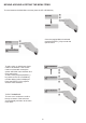
Connections (Vacon NXL) VACON NXL VSD CONNECTION Cable Length to be 1.5m from Speedman to VSD body.
TROUBLESHOOTING PROBLEM CAUSE 58 SOLUTION
PROBLEM Pump shutting down on Pump Protection Controller powers on and off continuously Can’t tune the set point above/Below a number System Displays wont initialise CAUSE • SOLUTION Fault in protection sensor • Voltage being applied to the Inputs. • Excessive current being drawn from the external pressure sensor • The set point must be between the Cut In pressure and the High Pressure limit • System needs to be initialised.
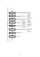
Site Record Main Menu Sub Menu Date / / / Set Point & Actual Pressure Flow Rate/min & VSD Spd FAULT HISTORY Fault 1 Fault 2 Fault 3 Fault 4 Fault 5 PUMP DATA LOG Flow Total Average Flow Rate Average Pressure Highest Pres Hours Run 1 Hours Run 2 Pump Starts 1 Pump Starts 2 Pump starts Last Hr Analogue Input 1 Analogue Input 2 Analogue Output 1 Analogue Output 2 Digital Input State M Digital Output State PID Error Curr & Max Retry Temperature Modbus Monitor Access Code 21 SETTINGS LoPress Shutdown
Main Menu Sub Menu TUNING Minimum Frequency Date Shutoff Head Response Rate (P) Accelaration HiPress Restarts Standby Boosts Standby Flow Min Error Correct (I) OvershootElim (D) RR (P) EC(I) OE(D) TIMING N/A N/A LoPressure Delay HiPressure Delay IN Delay Timer Out Delay Timer Restart Delay Standby Test Time Falback Delay Boost Hold Time Pump Fault Timer Input Delay Timer Press Trip Low Delay Press Trip High Delay Flow Trip Low Delay Flow Trip High Delay Stop Time Start Time CONFIGURATION Operating
Main Menu Sub Menu PUMP DEFINITION Pump 1 Date Pump 2 JOCKEY PUMP Jockey Pump Mode JP Cut In Pres JP Set Point JP Cut Out Pres JP Flow Rate JP Response Rate JP Acceleration JP Standby Test JP Standby Boost JP Standby Flow JP Run On Time JP Restart Delay JP Use Main SP JP Min Frequency JP ErrorCorr’t (I) JP OverShtElim (D) OUTPUTS Digital Output 1 Digital Output 2 INPUTS Program Input 1 Program Input 2 Program Input 3 Program Input 4 Program Input 5 Program Input 6 Program Input 7 Program Input 8
INDEX acceleration, 26, 37 access code, 21, 34 Access Code, 11, 34 Actual Pressure, 18 Adjust Pressure, 32 Analogue Input, 11, 15, 19, 20, 40, 45, 53, 59 Analogue Output, 11, 19, 20, 59 Automatic Zero, 5, 31 averaging, 32 Boost Hold Time, 29 calibrate, 5, 49 calibration, 32, 33, 49 CONFIGURE, 14, 30 constraints, 6 control parameters, 30 Cut In, 28 Cycle, 43 cycling, 40 Danfoss FC102 VSD, 54 Decimal Places, 31 Decimal resolution, 31 Digital inputs, 21 Digital Output Options, 39 Digital outputs, 21 disable a
Davey® Repair or Replacement Guarantee In the unlikely event in Australia or New Zealand that this Davey product develops any malfunction within one year of the date of original purchase due to faulty materials or manufacture, Davey will at our option repair or replace it for you free of charge, subject to the conditions below. Should you experience any difficulties with your Davey product, we suggest in the first instance that you contact the Davey Dealer from which you purchased the Davey product.