INSTALLATION MANUAL SERIES 9800 MARINE INTERCOM SYSTEM 19532P-62 (03-11) 2011 David Clark Company Incorporated
Table of Contents Cautions and Warnings ................................................................................................... 1 Parts/Tools List ............................................................................................................... 2 System Overview ............................................................................................................ 3 1. Mounting the Master Station .................................................................................
List of Figures (continued) Figure Page 13 C98-15RS Remote PTT Cable ..................................................................... 20 14 C98-20PW Cable w/40688G-47 2-Amp Fuse Kit ......................................... 22 15 C98-20PW Power Cable .............................................................................. 23 16 C98-20AX Auxiliary Audio Cable.................................................................. 25 17 Audio Isolation Transformer Circuit .....................
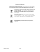
Cautions and Warnings READ AND SAVE THESE INSTRUCTIONS. Follow the instructions in this installation manual. These instructions must be followed to avoid damage to this product and associated equipment. Product operation and reliability depends on proper installation. DO NOT INSTALL ANY DAVID CLARK COMPANY PRODUCT THAT APPEARS DAMAGED. Upon unpacking your David Clark product, inspect the contents for shipping damage.
Parts/Tools List Supplied by David Clark q q q q q q q q q q q q q q q q q q q q q q q q q q q q U9800S U9810PD U9810BS U9811BS H9832 H9842 H9842BK H9842SK Master Station (P/N 40898G-01) Panel Display (P/N 40879G-01) Body Switch PTT (P/N 40895G-03) Body Switch PTT/Cell Phone (P/N 40895G-02) Headset OTH (P/N 40896G-02) Headset BTH (P/N 40897G-03) Headset BTH(black) (P/N 40897G-04) Headset BTH with Momentary (P/N 40897G-06) Mic Switch (black) H9842TM Headset BTH with Throat Mic (P/N 40897G-08) (black) C98-1
System Overview The Series 9800 Marine Intercom System is a weather-resistant communication system designed for the marine environment. It allows a captain, co-captain, and up to four passengers (six positions total) to communicate with each other over the intercom, and two of the members (captain and co-captain) to communicate over two mobile radios. Also available is an option to interface a third audio source such as a Stereo, CD player, or any other listen-only radio.
Figure 1: Typical 4-Person Layout 19532P-62 (03-11) 4 of 32
1.
Figure 2: Master Station mounting diagram 19532P-62 (03-11) 6 of 32
Figure 3: Master Station Mounting Template 19532P-62 (03-11) 7 of 32
This Page Left Intentionally Blank 19532P-62 (03-11) 8 of 32
Figure 4: Master Station Connections 19532P-62 (03-11) 9 of 32
2. Mounting the Panel Display The Panel Display is the control center for the David Clark Series 9800 Marine Intercom System. From here the user can adjust volume and sensitivity levels, as well as select which radio is active for transmitting. See section 10. Operation for complete details.
Procedure q Determine the location for the Panel Display. The Panel Display should be mounted on a flat surface that is visible and accessible to the captain and co-captain. The surface can range in thickness from 1/32 to 7/8 inches. See Figure 7. q Be sure there is at least 6-inches of room behind the panel to attach and route the C98-20PD Panel Display Cable. q Using the drilling template in Figure 8, mark the location for the 1 1/4” hole on the mounting surface.
This Page Left Intentionally Blank 19532P-62 (03-11) 12 of 32
Figure 8: Panel Display Mounting Template (Overall Clearance with Cover 4-1/2" Square) 19532P-62 (03-11) 13 of 32
This Page Left Intentionally Blank 19532P-62 (03-11) 14 of 32
3. System Cables System Cables interface David Clark Series H9800 Headsets to the Series 9800 Marine Intercom System. For convenience, there are two types of System Cables available, In-Line and Panel-Mount. The Series 9800 Intercom System can accommodate up to six headsets.
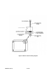
Procedure • Special note for C98-50LN: See Appendix A for connector assembly instructions . • For In-Line installation: • q Determine the location for the System Cable/Fitting. Maximum panel thickness is 7/32”. q Drill 27/32” hole in panel where System Cable is to be installed. q Remove mounting nut from cable fitting and put in a safe place. q Snake cable through hole from the outside (headset side) in.
5/32 TYP 1.500 1.
This Page Left Intentionally Blank 19532P-62 (03-11) 18 of 32
4. Radio Cables The C98-20RD Radio Cables are used to interface a marine or mobile radio to the Series 9800 Marine Intercom System. One end of the cable connects to the Master Station and the other end connects to the radio. Since the interface is different for each type of radio, the C98-20RD is left un-prepared at the radio end so that the installer may choose the correct interface. Note: This procedure applies only to the C98-20RD Radio Cable. Contact factory if assistance with other cables is needed.
5. Remote PTT (Optional) The Captain and Co-Captain positions provide the option for a Remote PTT switch, which can be mounted in a convenient location. The C98-15RS cable is finished with a connector on one end and a molded, waterproof switch on the other end, and a compression fitting. Note: This procedure applies to the C98-15RS Remote PTT Cable with built-in switch. Alternately, the C98-15CP or C98-30CP multi-use cables can be used for remote PTT.
Alternate Remote PTT Procedure: Parts/Tools Required q q q q q q q C98-15CP or C98-30CP Multi Use Cable (40892G-05 or 40892G-10) SPST or SPDT switch (user supplied) Marine grade connectors (as needed, for user supplied switch) Wire cutters and wire strippers Drill and drill bit (size dependant on switch used) Heat-shrink tubing Wire ties Procedure q Determine the location of the PTT switch. q Drill a hole the appropriate size for the switch selected.
6. Power Cable The C98-20PW is a 20-foot cable used to provide power to the Series 9800 Marine Intercom System. It has a connector on one end and the other end requires the installer to prepare. It is important to choose a power “pick-off” point which can provide 2 amperes of current at a voltage between 11-30VDC. Direct connection to a 2-Amp fuse/circuit-breaker is preferred.
q Connect the cable to the jack on the Master Station labeled “Power Cable”, see Figures 1&4. To connect the cable to the Master Station, align keyways and push. Then firmly turn collar clockwise until it locks into place. Pull back gently on the cable to ensure connector is properly locked.
7. Captain’s Priority Switch (Optional) The Captain’s Priority switch allows for the Captain to isolate himself along with Radio 1 and Radio 2 from the Co-Captain and the Passengers. When this switch is ON, the Captain will have exclusive access to Radio 1 and Radio 2. See section 10. Operation for complete details.
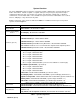
8. Auxiliary Audio Connection (Optional) The Auxiliary Audio connection is intended for use with line-level devices only. Typical connections include a portable CD/MP3 player’s headphone jack or the “Preamp Output” RCA jacks on a car/marine stereo. IMPORTANT: To connect to the External Speaker terminals of a communications or weather radio that has balanced audio output, an external transformer MUST be used to prevent possible damage to the radio and/or the Series 9800 Marine Intercom.
• For Weather/2-Way Radio Connection (Listen Only): q It is very important to follow these instructions carefully. Failure to do so may result in serious damage to your radio equipment or the Series 9800 Marine Intercom System. q Locate the Speaker/Audio outputs on the radio. Determine the method of connection (terminals, connector, etc.). q See Figure 18 & Table 3 which show how to connect an isolation transformer between the radio and the C98-20AX cable.
9. Connecting Headsets & PTT Switches Parts/Tools Required q q q H9832, H9842, H9842BK, H9842SK, or H9842TM headset(s) U9810BS/U9811BS Body PTT Switch(es) Completion of Series 9800 Marine Intercom System installation steps 1-8. Procedure q If a U9810BS or U9811BS is used, connect the Headset to the Body PTT Switch and to the System Cable, align keyways on each connector and push together. To disconnect just pull apart. Do not twist. See Figure 19.
10. Operation Panel Display MARINE INTERCOM MODE TX1 TX2 Figure 19: Panel Display Control The Panel Display is a user-friendly interface which allows the user to make several adjustments to the Series 9800 Marine Intercom System. It is the control center for the entire system. The included plastic cover should be used to protect the Panel Display when it is not in use.
Panel Display, Continued Transmit Select There is also a radio TX1/TX2 select button located on the front of the Panel Display to select which radio the captain and/or co-captain will transmit out on. To select the radio for transmit, simply push the TX1/TX2 button until the LED changes to the appropriate radio.
Advanced Features Captain’s Priority Switch The Captain’s Priority switch allows for the Captain to isolate himself, along with Radio 1 and Radio 2 from the Co-Captain and the Passengers. Table 5 shows the characteristics of the system when this feature is disabled, and Table 6 shows the operation when this feature is enabled. Captain’s Priority Disabled (Normal Operation) Radios 1&2 Aux.
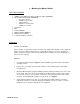
11. Testing & Troubleshooting Parts/Tools Required q q q Completion of the previous installation sections (1-9) in their entirety Read section 10. Operation An assistant (optional) Test Procedure q Double-Check all connections and wiring from the previous sections. q Complete connections of power cables to power source. q Turn on power at the pick-off point/source. q Set all Panel Display volume settings to level 6. q From each station verify that there is intercom communication.
Troubleshooting If the Panel Display does not function properly, it can be reset by either powering "OFF" the Series 9800 Marine Intercom System and then powering it "ON" or, by pushing the "Mode Button", the Arrow Down (↓) button, and the Arrow Up (↑) button, simultaneously. Symptom Cannot hear any audio in headset(s) Cannot speak over intercom Possible Cause(s) 1. 2. 3. 4. 1. 2.
Appendix A C98-50LN – 50-foot System Cable (P/N 40893G-12) INSTALLATION SHEET The C98-50LN System Cable interfaces a H9800-series headset with the David Clark Series 9800 Marine Intercom System, and allows for the installer to trim the length of the cable as needed. The installer must also attach the mating connector (P/N 13265P-55). This sheet provides instructions for the proper installation of this connector. The 13265P-55 Connector Kit contains the following items: 1. 2. 3. 4. 5. 6.
The connector pin numbers are as follows. Please note this is solder-socket view. Figure A1: Connector Pin Diagram, solder-socket view Function Mic Hi +9V Right Ear Ground PTT Hi Left Ear Shield Color Red White Green Black Orange Brown Shield Pin No.
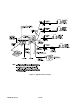
Appendix B P/N 40688G-47 Waterproof Fuse Kit Installation Instructions Parts/Tools Required • • • • • 1/8-inch diameter heat shrink tubing Wire strippers Crimp tool (Radio Shack P/N 64-409 or equivalent) Crimp terminals 2-Amp fuse kit Procedure 1. Using a heat gun, install 1/8" diameter heat shrink tubing* over one end of the 4" red wire (supplied). Install the second piece of 1/8" diameter heat shrink tubing over the red wire on the C98-20PW Power Cable. 2.
Appendix C Master Station Adjustments Radio 1 & Radio 2 Transmit Audio Level Adjustments Under most circumstances these adjustments have been pre-set to optimum levels and should never need to be performed in the field. However, they are included in this section should their adjustment be necessary. To increase or decrease the transmit mic audio level for Radio 1, locate and adjust R161 on the inside of the U9800S Master Station. For Radio 2, locate and adjust R179.
Auxiliary Input Balance Adjustments To modify the left/right balance of the auxiliary input, adjust R220 for the left channel and R206 for the right channel. Turning the potentiometer clockwise will increase the level. These components are also found inside the U9800S Master Station and can be located by examining Figures C1.
Figure C2: Jumper Locations 19532P-62 (03-11) C3
Appendix D Environmental Specifications The David Clark Series 9800 Marine Intercom System is designed to meet the following environmental requirements: 1. Temperature: -20 to +70 deg C Operational -40 to 85°C Storage 2. Humidity: 0 – 95% Non-condensing 4 cycles 96 hours 3. Salt Fog: MIL-STD-810E Method 509.3 96 hours in 5% NaCl solution 4. Shock: MIL-STD-810E Method 515.4 Sawtooth pulse 20 g 11 ms 5. Vibration: MIL-STD-810E Method 514.