INSTALLATION / OPERATION MANUAL SERIES 9100 DIGITAL INTERCOM SYSTEM
Table of Contents Cautions and Warnings .......................................................................................................................... iii 1. System Overview............................................................................................................................... 1 2. Mounting the Master Station ............................................................................................................ 3 Parts/Tools Required ..................................
Procedure.................................................................................................................................... 43 11. Add-In Cards.................................................................................................................................... 44 Adding/Removing Master Station Add-in Cards........................................................................... 44 Parts/Tools Required ........................................................................
Cautions and Warnings READ AND SAVE THESE INSTRUCTIONS. Follow the instructions in this installation manual. These instructions must be followed to avoid damage to this product and associated equipment. Product operation and reliability depends on proper installation. DO NOT INSTALL ANY DAVID CLARK COMPANY PRODUCT THAT APPEARS DAMAGED. Upon unpacking your David Clark product, inspect the contents for shipping damage.
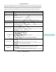
1. System Overview The Series 9100 Digital Intercom System is a configurable, weather-resistant, IP-based communication system suitable for use in all environments. It allows for wired and wireless users to communicate with each other and external audio equipment such as two-way radios, smart phones, other intercoms, and any other analog audio device with virtually unlimited configurability. Each user has a PTT button and 4 modes to select from called selections.
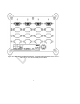
Figure 1.0.1 U9100 Digital Intercom Master Station – Populated with U9101 Switch Card in slot “A”. Slots “B”, “C”, and “D” have blank panels installed.
2. Mounting the Master Station Parts/Tools Required U9100 Series Digital Intercom System Master Station (44000G-01) M9100RM Rack-Mount Kit (44004G-01, optional) Pencil/Pen Drill 13/32-inch Drill Bit #8 Mounting Screws (customer supplied) Nuts (customer supplied) Lock-washers (customer supplied) Procedure Location Considerations Select a location on a flat surface that is out-of-the-way, and provides adequate room to attach all cables. The Master Station is immersion-proof (IP67).
3. Mounting Endpoints Parts/Tools Required U9100-series endpoint(s) (Headset Stations/Wireless Gateways) M9110FM Flush-Mount Kit (44004G-02, optional) Pencil/Pen Drill 13/32-inch Drill Bit #8 Mounting Screws (customer supplied) Nuts (customer supplied) Lock-washers (customer supplied) Procedure Location Considerations Select a location on a flat surface that is out-of-the-way, and provides adequate room to attach all cables. The U9100-series endpoints are immersion-proof (IP67).
Figure 3.1 U9110 Headset Station, shown with waterproof RJ-45 and headset connected Figure 3.
4. System Cabling System Cabling is used to interface David Clark Series 9100 Endpoints to the 9100 Digital Master Station. This cabling must be Ethernet Category 5e or higher. David Clark offers two types of cabling as well as two RJ-45 connector options depending on the application and location.
Slide all pieces together and hand-tighten SCN-17-02. Figure 4.2 Waterproof connector assembly Figure 4.
5. Radio Cables The C91-20RD Radio Cables are used to interface a marine or mobile radio to the 9100 Digital Intercom System. One end of the cable connects to a U9104 or U9102 installed in the Master Station and the other end connects to the radio. Since the interface is different for each type of radio, the C91-20RD is left un-prepared at the radio end so that the installer may choose the correct interface connector.
6. Power Cable The C91-20PW is a 20-foot cable used to provide power to the 9100 Digital Intercom System. It has a connector on one end and the other end requires the installer to prepare. It is important to choose a power “pick-off” point which can provide 10 amperes of current at a voltage between 11-30VDC. Direct connection to a 10-Amp fuse/circuit-breaker is preferred.
o o Connect the RED to the positive (+) terminal. Connect the BLACK and SHIELD to the negative (-) terminal. 7. Auxiliary Audio The Auxiliary Audio connection is intended for use with line-level devices only. Typical connections include a portable CD/MP3 player’s headphone jack or the “Preamp Output” RCA jacks on a car/marine stereo. This cable can also be used to route audio from the Digital Intercom System to another device (such as a camera or recorder) .
8. Operation and Programming The Series 9100 Digital Intercom System has a variety of programming options and can satisfy virtually every configuration application. See the information and examples below for details. Headset Stations The U9110-series headset stations provide a fixed-position, wired interface into the U9100 Digital Intercom System.
Wireless Wireless Gateway The U9120-series Wireless Gateways provide an un-tethered interface into the U9100 Digital Intercom System. Each Wireless Gateway can be linked with up to four U91xxBSW belt stations.
Wireless Belt Stations Pressing and holding the Power button for approximately 5 seconds will power on/off the Wireless Belt Station. Linking Linking is accomplished by momentarily pressing the LINK button on the Wireless Gateway and the PTT button on the Wireless Belt Station. The Wireless Gateway and the Wireless Belt Station must be within approximately 1 to 3ft (0.5 to 1m) of each other in order for linking to be successful. This “close-link” mechanism prevents other devices from being linked.
Figure 8.
User Interface 1. Once power is turned on to the system in about 30 seconds the web interface will be available. 2. The factory default IP address is 192.168.2.1 and authentication is disabled. 3. Connect a computer via Ethernet cable to an open switch card port. If all switch card ports are used, a PoE splitter such as CyberData #011187 or a PoE capable Ethernet switch may be used. 4. Open a web browser and go to http://192.168.2.1 5.
Setup Wizard Figure 8.5 1. Each device detected on the system is shown, as well as any add-in cards present in the Master Station. 2. Clicking on a device expands a pane with its properties and settings. 3. A Headset Station or Wireless Gateway Station has the following options: icon a. Rename by clicking the icon (all LEDs on the device will turn solid red for 10s) b. Identify by clicking the c. LED mode. Can be set to Normal or Dark. See Figure 8.6. d. VOX mode. Can be set to PTT, Auto, or Hot Mic.
Figure 8.6. 4. A Radio Card or Radio/Aux Card can have its channels renamed and levels adjusted. Audio level adjustments should not be made now. Instead, make these adjustments after talk group setup is complete. See Figure 8.
Figure 8.7 5. The Master Station and Switch Cards do not have any configurable options but their properties can be viewed. 6. Once all renaming and settings have been made, click NEXT. The Auto-Configure page will be displayed. See Figure 8.8.
Figure 8.8 7. On the Auto-Configure page, select all the devices that you want to use on this system. Note that if you are connected to a LAN, there may be devices on the network that you do not wish to configure. In most cases however, you should check “Select All”. 8. Once you have selected the devices, click “Auto Configure Now”.
Figure 8.9 10. Once Auto-Configure is complete, click NEXT. The system will reinitialize with the new settings. Once complete, the Configure Talk Groups page will be displayed. 11. Click “Add New Talk Group” and click the talk group name to expand it. See Figure 8.10.
Figure 8.10 12. In the pane you will see all of the devices you selected to Auto Configure, plus any Radio Cards or Radio/Line cards installed in the Master Station. icon. 13. The talk group may be renamed by clicking the 14. For detailed talk group programming and examples, see Talk Group Programming.
Device Management Clicking DEVICE MANAGEMENT will display a list of all devices detected on the network and all add-in cards installed in the Master Station.
Figure 8.11: System Status Configuration Type There are three IP Configuration types available: • DHCP Server o The Master Station will auto-assign IP addresses to other network devices connected. o Use this option if the system will be operated in a stand-alone environment and not connected to an existing network. • DHCP Client (default) o The Master Station will look for a DHCP server on the network and use an IP address provided by the DHCP server.
Additional Networking Options • • • Hostname: A host name to identify this device on the network. DHCP Server, Smart DHCP, or Static IP the following options apply: o IP Address o Subnet Mask o Gateway o DNS Server o DHCP Pool Start (not applicable for Static IP) o DHCP Pool Size (not applicable for Static IP; Number of addresses to assign) Click Save IP Config to save changes. The system must be restarted for most settings to take effect.
Talk Group Programming Talk groups are where most of the settings for the system will be made. Talk groups are a method of presenting the powerful options of the system to the user in a straight-forward and intuitive way. Each Headset Station or Wireless Belt Station is capable of (4) Selections as well as a PTT button. Talk groups are configured such that different combinations of selection and PTT pressed/not pressed can have different settings.
Talk Group Example 1: Multiple users on intercom, hot mic • • Multiple users talking and listening to each other Users can be on any selection (1-4) and do not have to press PTT to be heard Steps 1. 2. 3. 4. 5. 6. 7. 8. 9. Click Add New Talk Group. Rename talk group if desired by clicking . Click to expand each Headset Station or Wireless Gateway you wish to add to this group. To identify a device, click the and all LEDs on the device will turn red for 10 seconds.
Talk Group Example 2: Multiple users on intercom, press PTT to talk • • Multiple users talking and listening to each other. Users can be on any selection (1-4) but must press PTT in order to be heard by others. Steps 1. 2. 3. 4. Create a new talk group. Click to expand each Headset or Wireless user you wish to add to this group. Under Outputs select All Rx. For wireless, select Ear.
Talk Group Example 3: Multiple users on hot-mic intercom, press PTT to talk over radio • • • Multiple users talking to each other freely (no PTT) Press PTT to talk over radio Selection may be anything (1-4) Steps 1. 2. 3. 4. 5. 6. 7. 8. 9. 10. 11. 12. 13. Create a new talk group and rename it “Intercom” Click to expand each Headset or Wireless user you wish to add to this group. Under Outputs select All Rx. For wireless, select Ear. Under Inputs select Mic.
Figure 8.
Figure 8.
Talk Group Example 4: Intercom, multiple radios • • • Users can talk freely on intercom when on selection 1 or 2 Users hear and talk over Radio 1 when on selection 1 Users hear and talk over Radio 2 when on selection 2 Steps 1. 2. 3. 4. 5. 6. 7. 8. 9. 10. 11. 12. 13. 14. 15. 16. 17. 18. 19. 20. Create a new talk group and name it “Intercom”. Expand the Headset or Wireless users to be part of this group. For each Headset/Wireless user, expand Headset/Wireless User to reveal the selections.
Figure 8.
Figure 8.
Figure 8.
Talk Group Example 5: Aux-in + Smart phone with ducking • • • • Users can hear auxiliary audio from a music device or optionally, a smart phone. Users can press PTT to play/pause/answer/hang-up phone (if supported by phone). Users can talk over the phone. If a user speaks, the phone audio mutes in favor of the speaking user’s audio. Steps 1. 2. 3. 4. 5. 6. 7. 8. 9. 10. 11. 12. 13. 14. 15. 16. 17. 18. Follow Talk Group Example 1 to create a talk group named “Intercom”.
Figure 8.
Figure 8.
Figure 8.
Figure 8.22 Talk Group Example 5 – PTT Headsets Donning/Positioning Each Headset should be worn so that the ear seals fit snugly against the head, and the ears are fully enclosed within the inside of the ear seals. Adjust the microphone boom so that the microphone is positioned no more than ¼” from the lips. Using the Headset in this manner ensures optimal performance, especially in high-noise environments.
PTT Switches The H9100-series Headsets have PTT switches conveniently located on the mic boom, just behind the microphone. These can be used to transmit over a talk group or a two-way radio, redundant to the PTT switches found on the Headset Station or Wireless Belt Station.. See 8. Operation and Programming for more information.
9. Testing & Troubleshooting Parts/Tools Required Completion of the previous installation sections in their entirety An assistant (recommended) Test Procedure Double-check all connections and wiring from the previous sections. Complete connections of power cables to power source. Turn on power at the pick-off point/source. Connect a computer/laptop via Ethernet cable to one of the switch card ports on the Master Station.
Symptom Cannot access web user interface Possible Cause(s) 1. 2. 3. 4. 1. Device(s) missing on 2. DEVICE MANAGEMENT 3. Not able to communicate to other users/radios as expected Radio audio problem (low/high/distorted/etc.) Muffled audio/high background noise Is power applied to Master Station? Allow 30s for complete boot up.
10. Fuse Kit P/N 41090G-22 Waterproof Fuse Kit Installation Instructions Parts/Tools Required 1/8-inch diameter heat shrink tubing Wire strippers Crimp tool (Thomas & Betts WT-11-M or equivalent) Crimp terminals 10-Amp fuse kit Procedure Using a heat gun, install 1/8" diameter heat shrink tubing* over one end of the 4" red wire (supplied). Install the second piece of 1/8" diameter heat shrink tubing over the red wire on the C91-20PW Power Cable.
11. Add-In Cards Adding/Removing Master Station Add-in Cards To add or remove an add-in card the Master Station must be opened. The procedure below must be followed correctly to maintain IP67 integrity and to prevent damage to the Master Station and Add-in Cards. Parts/Tools Required #1 and #2 Philips bits Torque wrench capable of measuring 2 - 6 lbf-in (20 - 70 N-cm) of torque Procedure IMPORTANT: Failure to observe torque specifications will result in a compromise of IP67 integrity. Disassembly 1.
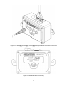
Figure 11.1 Main Cover Assembly Figure 11.2 Power Connection Figure 11.3 Main PCB and Add-In Card Assemblies Figure 11.
12. Technical Specifications ELECTRICAL Power Requirements Power Distribution 11-30VDC (10A max., depending on system configuration) Power-over-Ethernet (802.
FCC NOTICE (for U.S. Customers): This device complies with Part 15 of the FCC Rules: Operation is subject to the following conditions: 1. This device many not cause harmful interference, and 2. This device must accept any interference received, Including interference that may cause undesired operation Changes and Modifications not expressly approved by DAVID CLARK COMPANY INC. can void your authority to operate this equipment under Federal Communications Commissions rules.