
User's Manual

8
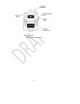
5. Radio Cables
The C91-20RD Radio Cables are used to interface a marine or mobile radio to the 9100 Digital Intercom
System. One end of the cable connects to a U9104 or U9102 installed in the Master Station and the
other end connects to the radio. Since the interface is different for each type of radio, the C91-20RD is
left un-prepared at the radio end so that the installer may choose the correct interface connector.
Parts/Tools Required
C91-20RD Radio Cable (One for each radio to be interfaced)
A U9104 or U9102 radio card installed in the Master Station
Mating connector and pin information for radio interface (installer provided)
o Wire Crimping/Cutting/Soldering/etc. tools (depends on radio interface)
Wire ties
Procedure
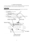
Determine the path of the cable between each radio and the Master Station. The radios should
already be installed and tested.
Route the cable. The cable should be routed using conduits and be as far as possible from radio
antenna coax cables and anywhere water may collect. The connector end connects to the
appropriate radio card as installed in the Master Station. Leave enough excess cable at the
radio end for preparation of radio interface connector.
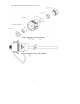
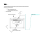
Connect the cable to one of the radio card inputs on the Master Station; Align red keyways and
push. Pull back gently on the connector (behind the quick-release collar) to ensure it is properly
locked.
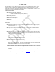
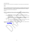
Prepare the radio interface in accordance with manufacturer’s instructions. See Table 5.1 for
C91-20RD Radio Cable wire color functions. The end of this cable is stripped and tinned at the
factory. Due to the difficulty in soldering to these conductors, it is recommended that any extra
cable be coiled up rather than cut.
Repeat this procedure for additional radios.
Pin
Color Function
1
Red Mic Hi (+)
2
White Mic Lo (-)
3
Green Ear Hi (+)
4
Black Ear Lo (-)
5
Yellow PTT Hi (+)
6
Blue PTT Lo (-)
Shield Shield (To PTT Lo or Mic Lo)
Figure 5.1 Radio Cable Wire Color Functions