Integrated Sensor Suite Installation Manual For Vantage Pro2™ & Vantage Pro2 Plus™ Weather Stations Davis Instruments, 3465 Diablo Avenue, Hayward, CA 94545 • 510-732-9229 • www.davisnet.
Contents Introduction ....................................................................................................... 1 Included Components and Hardware ................................................................ 1 Cabled ISS Assembly ........................................................................................ 7 Wireless ISS Assembly ..................................................................................... 9 Preparing the ISS for Installation ............................
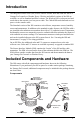
Introduction The Integrated Sensor Suite (ISS) collects outside weather data and sends the data to a Vantage Pro2 console or Weather Envoy. Wireless and cabled versions of the ISS are available, as well as Standard and Plus versions. The Wireless ISS is solar powered and sends data to the console via a low-power radio. The Cabled ISS sends data and receives power via the console cable. The Standard version of the ISS contains a rain collector, temperature sensor, humidity sensor and anemometer.
Preparing the ISS for Installation Note: If the ISS is a Plus model and contains UV and solar sensors, do not touch the small white diffusers on top of the sensors. Oil from skin reduces their sensitivity. If you are concerned that you have touched the diffusers at any time during the installation, clean the UV diffuser using ethyl alcohol with a soft cloth. When cleaning the UV diffuser, DO NOT use rubbing or denatured alcohols because they can affect accuracy of the sensor readings.
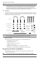
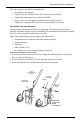
Preparing the ISS for Installation The steps to prepare the ISS for installation are: • Assemble the anemometer. • Check the factory-installed sensor cable connections to the SIM. • Connect the anemometer sensor cable to the SIM. • Apply power to the ISS and test communication with the console. • Change the Transmitter ID for wireless communication, if necessary. Assemble the Anemometer The anemometer measures wind direction and speed.
Check SIM Sensor Connections 4. Slide the tooth-lock washer and hex nut onto the machine screw. Tighten the hex nut while holding the screw with a Phillips head screwdriver to prevent it from turning. 5. Press the sensor cable firmly and completely into the zig-zagging channel in the base, starting from the arm and progressing downward to the bottom of the base. Be sure to press the cable into the channel at the bottom of the groove.
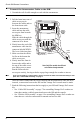
Check SIM Sensor Connections Open the SIM Box 1. Locate the white box with the solar panel containing the SIM on the front of the ISS unit. The cabled model does not have a solar panel. 2. Locate the white tab at the bottom center of the SIM box cover. 3. Lift the tab away from the box while sliding the cover up. Look on the side of the SIM box. The box cover can be easily removed from the box when the alignment indicator on the cover is lined up with the alignment indicator on the box 4.
Check SIM Sensor Connections Connect the Anemometer Cable to the SIM 1. Unwind the coil of cable enough to work with the anemometer. Note: Do not unwind the entire coil of anemometer cable at this time. 2. Pull the foam insert out of cable access port in between the cables and set the foam insert aside. 3. Insert the anemometer Sensor cable end into the cable Interface Module access port from beneath (SIM) the SIM box. Slide the cable through the cable access port with the connector lever down. 4.
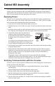
Cabled ISS Assembly The Cabled ISS system contains a cable for connecting the ISS to a Vantage Pro2 cabled console. Once the anemometer has been installed and the sensors have been checked, a cabled connection between the ISS and the console can be established. Follow the steps below for powering the ISS and connecting to the console. Applying Power The 100' (30 m) console cable provides power to the ISS and is used to send data from the ISS to the console.
Troubleshooting Cabled ISS Communication Approximately one minute after power-up the outside relative humidity reading should be displayed on the console. 5. If the ISS contains a UV sensor and/or solar sensor, press 2ND and then press RAIN YR for current ultraviolet readings or press 2ND then press RAIN DAY for solar radiation readings. The UV reading displays in the center of the console. The solar reading displays in the bottom right corner of the console display.
Wireless ISS Assembly The ISS has a wireless connection to a Vantage Pro2 wireless console. Once the anemometer has been installed and the sensors have been checked, the ISS must be powered and a wireless communication channel must be established between the ISS and the console. Follow the steps below for powering the ISS and establishing a connection to the console.
Verifying Data from the ISS Sensors Verifying Data from the ISS Sensors Use these steps to verify reception of ISS data at the wireless Vantage Pro2 console and to test the operation of the ISS sensors. 1. Press and hold DONE until the Current Weather screen displays, if the console is in Setup Mode. Sensor readings from the ISS should display on the screen. 2. Near the center of the screen, look for the outside temperature. 3.
Troubleshooting Wireless ISS Reception Note: If the LED is flashing rapidly, call Technical Support. See “Contacting Davis Instruments” on page 27 for more information. 5. 6. 7. 8. Note: See “SIM Board Display and Contents” on page 30 for information on locating the components and points of interest on the SIM board. If the LED remains dark, there is a problem with the ISS transmitter. Call Technical Support. See “Contacting Davis Instruments” on page 27.
Troubleshooting Wireless ISS Reception ON 1 2 3 4 DIP Switches Transmitter ID DIP Switches in Top-right Corner of SIM To change to another ID, use a ballpoint pen or paper clip to toggle DIP switches #1, 2, and 3. The settings for Transmitter IDs 1 - 8 are shown in the table below. Set the Vantage Pro2 console to the same ID as the transmitters, as described in the Vantage Pro2 Console Manual.
Preparing the ISS for Installation Once all the sensors have been connected and communication between the ISS and the console has been successfully established, continue to prepare the ISS unit for installation. The steps for preparing the ISS for installation are as follows. • Close the SIM Box • Prepare the Solar Panel • Prepare the Rain Collector • Site the ISS and Anemometer Close the SIM Box To close the SIM box and continue assembling the ISS: 1.
Prepare the Rain Collector 4. While watching the daily rain display, tip the bucket until it drops to the opposite side, then wait two seconds to see if the display registers a rain reading. Each tip indicates 0.01" of rain and may take up to a minute to register at the console. If the bucket is tipped too quickly, the number on the console display may not change. 5. Temporarily reinstall the rain collector cone until you are ready to mount the ISS outside.
Locating the ISS and Anemometer 5. Slide the magnet, exposed end of magnet first, into the open slot of the metric adapter. 6. Insert the metric adapter and magnet between the arms of the bucket, with the solid side of the metric adapter facing up. Open plastic arms to insert metric measurement adapter, with adapter in “V” position Note: The above procedure converts the collector to 0.2 mm measurements. The console must be set accordingly. See the Vantage Pro2 Console Manual for more information.
Locating the ISS and Anemometer For agricultural applications (Important for evapotranspiration (ET) calculations): • Install the ISS and anemometer as a single unit with the radiation shield 5' (1.5 m) above the ground and in the middle of the farm between similar crop types (i.e. two orchards, two vineyards or two row crops), if possible. • Avoid areas exposed to extensive or frequent applications of agricultural chemicals (which can degrade the sensors). • Avoid installation over bare soils.
Locating the ISS and Anemometer Optional: Anemometer Cable Length Considerations • All Vantage Pro2 stations include a 40' (12 m) cable to go between the ISS and the anemometer. This can be extended up to 540' (165 m) using optional extension cables purchased from Davis Instruments. • If most of the anemometer cable length is unused, the coiled cable length can be stowed once the anemometer and ISS have been installed on a site.
Locating the ISS and Anemometer (( ( (( ( If your ISS is directly overhead, the orientation illustrated here might work best. For best reception, orient antennas so they are parallel to each other. • If possible, align the pivot joints of both the ISS and the console antennas so that they are facing each other for maximum signal strength. • The ISS and console antennas do not rotate in a complete circle. Avoid forcing the antennas when rotating it.
Installing the ISS The anemometer and the main part of the ISS can be installed either together as a single unit on a pole, or apart from each other. The main part of the ISS includes the rain collector, the temperature and humidity sensors, the radiation shield, and the SIM housing. Use the U-bolts to install the ISS and anemometer together or separately on a pole. Use the lag screws to install them separately on a flat, vertical surface.
Installing the ISS on a Flat Surface Installation Instructions There are several ways to mount and install the ISS unit. The following are installation types that Davis Instruments recommends. Individual ISS locations and installations may vary. • Installing the ISS on a flat surface • Installing the Anemometer on a post or flat surface • Installing the ISS on a pole Note: All installations require that the rain collector cone be removed for assembly.
Installing the ISS on a Pole Option 2: Installing the Anemometer on a Post or Flat Surface 1. With a 3/16" (5 mm) drill bit, drill two holes approximately 2-1/8" (54 mm) apart. Use a carpenter’s level to ensure the holes will be level. 2. Insert the 1/4" x 3" lag screws through the flat washers and the holes in the anemometer mounting base into the post. 3. Tighten the lag screws using an adjustable wrench or 7/16" wrench.
Installing the ISS on a Pole Guidelines for Installing the ISS on a Pole • When mounting both sides together, remember that whichever side of the ISS is mounted first, the U-bolt from the opposite side must also be placed around the pole before tightening the U-bolts. (If it is not, there is no way to slide it in later.) • In each side’s mounting base, there is a groove to accommodate the other’s U-bolt.
Finishing the Installation 3. Tighten the hex nuts using an adjustable wrench or 7/16" wrench. 4. Re-attach the rain collector cone. Set the cone back on the base so its latches slide downward into the latch openings on the base. Rotate the cone clockwise. 5. Place the debris screen (shown in the illustration on page 1) inside the cone, “feetdown,” over the funnel hole. Option 3: Installing Anemometer Only 1.
Additional Mounting Options Extending the Console Cable (Cabled ISS Only) A Cabled ISS can be extended up to 1000' (300 m) away from the console by using Davis Instruments extension cables (#7876). Relocating the Anemometer Using Extension Cables: Note: Not all cables are compatible with your Vantage Pro2 system. To be sure they will work, order Davis extension cables from your dealer or directly from Davis Instruments.
Maintenance and Troubleshooting Maintaining UV and Solar Radiation Sensors If the ISS is a Plus model and contains UV and solar radiation sensors, do not touch the small white diffusers on top of the sensors. Oil from skin reduces their sensitivity. If you are concerned that you have touched the diffusers at any time, clean the UV diffuser using ethyl alcohol with a soft cloth. When cleaning the UV diffuser, DO NOT use rubbing or denatured alcohols because they can affect accuracy of the sensor readings.
Troubleshooting Note: For some models of the ISS, the order in which the five radiation shield plates are assembled may be slightly different than the order shown in the figure on page 25. For this reason, ensure that you always reassemble the plates in the same order in which they were disassembled. 4. Reassemble the plates in the same order in which they were disassembled, and fasten them together using a Phillips head screwdriver to tighten the 4” screws, as shown in the illustration.
Troubleshooting “The wind cups are spinning but my console displays 0 mph.” The signal from the wind cups may not be making it back to the display. Remove the cups from the anemometer (loosen the set screw). Put the cups back onto the shaft and make sure to slide them up the shaft as far as possible. Check your cables for visible nicks and cuts. Look for corrosion in the WIND connector on the SIM and on splices in the cable. If using an extension cable, remove it and test using only the anemometer cable.
Appendices Appendix A: Re-orienting the Wind Vane • • • • The Vantage Pro2 station is configured to register wind direction correctly if the anemometer points to true north. If the anemometer shaft cannot be mounted to point to true north, use the following instructions to correct the wind vane orientation. Do not rely on a compass unless it is properly calibrated. In North America there can be up to 15° variation between true north and a raw compass reading.
Appendix B: Specifications Tighten set screw with Allen wrench Installing Wind Vane on Anemometer Shaft 11. Test the anemometer by pointing the wind vane in any direction and making sure the console displays the correct wind direction. Remove and re-adjust the vane if it does not. Allow the wind direction display approximately 5 seconds to stabilize after turning the shaft.
SIM Board Display and Contents SIM Board Display and Contents 2 1 3 4 5 + - 6 7 SENSOR INTERFACE MODULE UV 12 SUN RAIN WIND TEMP HUM 11 10 9 8 1 Solar Panel Tab 7 Test LED 2 AC Adapter Socke t 8 Temperature/Humidity Sensor Connector 3 Battery Socket 9 Wind Sensor Connector 4 Cabled Connection 10 Rain Sensor Connector 5 Transmitter ID DIP Switch 11 Solar Radiation Sensor Connector 6 Test DIP Switch 12 UV Sensor Connector 30