Long Range Repeater Installation Addendum For AC-Powered and Solar-Powered Long Range Repeaters Models 7653 and 7654
FCC Part 15 Class B Registration Warning This equipment has been tested and found to comply with the limits for a Class B digital device, pursuant to Part 15 of the FCC Rules. These limits are designed to provide reasonable protection against harmful interference in a residential installation. This equipment generates, uses, and can radiate radio frequency energy and, if not installed and used in accordance with the instructions, may cause harmful interference to radio communications.
Welcome! The Vantage Pro2™ Long Range Repeater can be used with any Vantage Pro2 wireless transmitter station and re-transmits the information to a Vantage Pro2 compatible receiver (Vantage Pro2 console or Envoy® or another Vantage Pro2 Wireless Repeater). The Long Range Repeater works in much the same way as the Vantage Pro2 wireless repeater, but extends the distance between a repeater and a receiver by up to 10 times that of the Vantage Pro2 wireless repeater (#7626 and 7627).
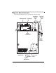
Repeater Board Contents The board contained within the repeater enclosure has the following contents: Solar Power Tab AC Adapter Transmitting Antenna Cable Receiving Antenna Cable Battery Compartment External Antenna Connectors Status TX LED LED 1 2 3 4 5 6 7 8 Transmitter DIP Switches Repeater Test Switch Repeater DIP Switches 2 First In Chain Jumper
The components unique to the Long Range Repeater board are: • Transmitting Antenna Cable — Connects the repeater to the external transmitting antenna. • Receiving Antenna Cable — Connects the repeater to the external antenna receiving a station or repeater signal.
Yagi (Directional) Antenna (#7660) The Yagi antenna includes the directional antenna and mounting hardware: Yagi Antenna 48" Antenna Cable 5/16" U-Bolts Flat Washer Lock Washer Nut Antenna Uses The Omni and Yagi antennas transmit and receive with two different radiation patterns.
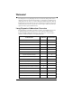
Antenna Ranges Each antenna type in a repeater network varies in the distances it can receive and transmit data. For instance, the dipole antenna on an ISS station transmitting to a dipole antenna on a console is limited to 1000'. A dipole transmitting to an external omni antenna lengthens the distance to 1580', because the distance can now be 1.58 times greater between an omni antenna and a standard dipole than it could with two standard dipole antennas.
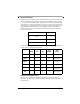
The legend below describes the antenna types and how they will be represented in a sample antenna configuration: Antenna Topology Legend Antenna Symbol Antenna Type Vantage Pro2 Console Weather Envoy Vantage Pro2 Wireless Repeater Any Vantage Pro2 Station Omni-directional Long Range Repeater Antenna Yagi (Directional) Long Range Repeater Antenna 6
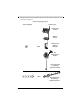
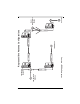
The first symbol represents any station/receiver/repeater with a normal dipole or long range omni antenna. The second symbol represents the long range Yagi antenna. The diagram on the next page contains all the long range external antenna configurations available for a network. In this example, there are four repeaters, each with a unique station-to-repeater or repeater-to-repeater antenna relationship.
8 Transmitting Temperature Station Leaf\Soil Station A Receiving B ISS Station C Representitive Antenna Configurations D Console Soil\ Temperature Station
Mounting the Repeater and External Antennas The antenna configuration and wireless repeater can be mounted on a pole at a designated location. Use the provided U-bolts for the wireless repeater and the U-bolts provided for each antenna type to install them all to a pole. Note: To accommodate your antenna configuration (omni and Yagi or Yagi and Yagi), mount the antennas first before mounting the wireless repeater enclosure.
4. Using an adjustable wrench or 1/2" wrench, tighten the nuts. 5. Place the second U-bolt around the pole and through the two holes at the bottom of the shelter. 6. Put a flat washer, a lock washer, and a hex nut on each bolt end, and tighten the hex nuts so that the Yagi remains in place, but can still be adjusted. 7. Rotate the Yagi so that is points to the desired station/repeater/receiver. 8. Tighten the hex nuts so that the Yagi is firmly attached. 9.
4. Using an adjustable wrench or 1/2" wrench, tighten the nuts. 5. Place the second U-bolt around the pole and through the two holes at the bottom of the shelter. 6. Put a flat washer, a lock washer, and a hex nut on each bolt end, and tighten the hex nuts so that the Yagi remains in place, but can still be adjusted. 7. Rotate the Yagi so that is points to the desired station/repeater/receiver. 8. Tighten the hex nuts so that the Yagi is firmly attached. 9.
Connecting External Antennas to the Repeater Once the repeater, and both external antennas have been attached to a pole and positioned, the antennas should be attached to the respective antenna cables in the wireless repeater enclosure. To do this: 1. Thread each antenna cable into the individual black cable grommets at the bottom of the shelter to provide weather-resistant entrances for cables. Make sure that there is one antenna cable per grommet.
Specifications Complete specifications for all of the Vantage Pro2 weather products as well as the wireless repeater are available in the Weather Support section of our website: http://www.davisnet.com/support/weather/ General Operating Temperature. . . . . . . . . . . . . . -40 to 150° Fahrenheit (-40 to 65° Celsius) Non-Operating Temperature . . . . . . . . . . -40 to 150° Fahrenheit (-40 to 65° Celsius) Current Draw . . . . . . . . . . . . . . . . . . . . . 1.
Transmit Interval Repeater Transmit Interval . . . . . . . . . . . 2.5625 - 3.0000 per ID. Wireless Communication (US models) Transmit/Receive Frequency . . . . . . . . 902-928 MHz FHSS. ID Codes Available . . . . . . . . . . . . . . . . 8 Output Power . . . . . . . . . . . . . . . . . . . . 902-928 MHz FHSS: FCC-certified low power, less than 8 mW, no license required. Type Gain Omnidirectional Antenna (#7655) 5 dBi Yagi Antenna (#7660) 11 dBi Range Line of Sight . . . . . . . . . . . . . . . . . .