
Installation manual


7
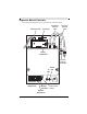
The first symbol represents any station/receiver/repeater with a normal dipole or long
range omni antenna. The second symbol represents the long range Yagi antenna.
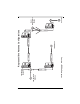
The diagram on the next page contains all the long range external antenna configurations
available for a network. In this example, there are four repeaters, each with a unique sta-
tion-to-repeater or repeater-to-repeater antenna relationship.
Repeater A has two Yagi antennas, the first antenna receiving data packets from an ISS
station with the standard dipole omni antenna. The transmitting Yagi antenna is sending
the data packets to Repeater B.
The receiving antenna on Repeater B is an omni antenna, that is collecting data from not
only repeater A, but also from two other stations in different directions. The transmitting
Yagi antenna is in direct line to the Yagi antenna on Repeater C.
The transmitting antenna on Repeater C is also a Yagi antenna. Repeater C is also sharing
a line of sight to Repeater D’s receiving Yagi antenna with another station. The omni
transmitting antenna on Repeater D is in range of the console.
Decide which configuration or multiple antenna configurations works best for your net-
work before mounting and installing your long range wireless repeaters.