General-Duty & Heavy-Duty Installation Manual Product # 8156GD, 8156HD
&217(176 Introduction . . . . . . . . . . . . . . . . . . . . . . . . . . . . . . . . . . . . . . . . . . . . . . . . . . . . . . . . 1 Components . . . . . . . . . . . . . . . . . . . . . . . . . . . . . . . . . . . . . . . . . . . . . . . . . . . . . 1 Additional Documentation . . . . . . . . . . . . . . . . . . . . . . . . . . . . . . . . . . . . . . . . . . 3 Tools and Materials Needed . . . . . . . . . . . . . . . . . . . . . . . . . . . . . . . . . . . . . . . . 3 Planning Your Installation . . . . .
07395.043 DR GD Inst Rev D Body D146.fm Page 1 Monday, December 1, 2003 12:02 PM , 1752'8&7,21 This manual provides installation instructions for the DriveRight 600 GD (General Duty), *' , and DriveRight 600 HD (Heavy Duty), +'. Since the specific installation details vary quite a bit from one vehicle to another, these instructions are intended to be a general guide for professional installers or for knowledgeable and experienced mechanics.
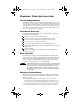
07395.043 DR GD Inst Rev D Body D146.fm Page 2 Monday, December 1, 2003 12:02 PM +DUQHVV DQG $GDSWHU &DEOHV Digital Input Adapter Cable Harness Cable :LULQJ Red +12V Wire with Fuseholder (22 AWG) Spade Terminal Sets #8-10 Studs 1/4" Studs (3.5 - 5 mm) (6 mm) Butt Splices (8) (26-22AWG or 24-20AWG) Black Ground Wire (22AWG) Blue Wire (2) with Fuseholder (22 AWG) Fuses (4) (3AG 1-1/4 x 1/4", .
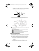
07395.043 DR GD Inst Rev D Body D146.fm Page 3 Monday, December 1, 2003 12:02 PM 'ULYH5LJKW +' 0DJQHW The DriveRight HD speed sensor magnet includes the following components. See “Supplement for DriveRight HD” on page 20. ❏ ❏ ❏ ❏ Stainless Steel Cable Tie Stainless Steel Magnet Mount Magnet Neoprene Rubber Strip $GGLWLRQDO 'RFXPHQWDWLRQ Refer to the following documents for additional information on configuring and using your DriveRight: ❏ The User’s Guide included with your DriveRight.
07395.043 DR GD Inst Rev D Body D146.fm Page 4 Monday, December 1, 2003 12:02 PM 3 /$11,1* <285 , 167$//$7,21 +RZ 'ULYH5LJKW :RUNV DriveRight GD and HD use a a reed switch and rotating magnet to sense vehicle speed. The speed sensor mounts on the driveshaft for rear wheel drive vehicles or on one of the in-board CV-joint hubs for front wheel drive vehicles. Each time the magnet passes the reed switch, the speed sensor sends a signal to console.
07395.043 DR GD Inst Rev D Body D146.fm Page 5 Monday, December 1, 2003 12:02 PM Often you can route the sensor wires through an existing feedthrough in the firewall. ❏ Decide where to install the harness cable and where to connect the power and ground leads. (Procedure 2) Find a location inside the vehicle where you can bring together the harness cable leads, the power and ground tap wires, the adapter cable leads, and the sensor cable leads.
07395.043 DR GD Inst Rev D Body D146.fm Page 6 Monday, December 1, 2003 12:02 PM , 167$//,1* ' 5,9( 5 ,*+7 &$87,21 Always use safety stands when working under a raised vehicle. Never work under a vehicle supported only by a jack. 3URFHGXUH ,QVWDOO WKH 6SHHG 6HQVRU The speed sensor used by the DriveRight GD and HD consists of a magnet mounted on the driveshaft or CV-joint hub and a reed switch. 1. Mount the magnet on the vehicle’s driveshaft or CV-joint hub. 2. Assemble the reed switch bracket. 3.
07395.043 DR GD Inst Rev D Body D146.fm Page 7 Monday, December 1, 2003 12:02 PM Place the magnet in its mount, then slide the large tie wrap through the magnet mount to keep the magnet in place as shown below. Tie Wrap Vehicle Driveshaft Magnet Magnet Mount Loosely cinch the large tie wrap around the drive shaft, with the magnet mount oriented as shown. 1RWH Keep the tie wrap slightly loose so you can adjust the position after installing the reed switch.
07395.043 DR GD Inst Rev D Body D146.fm Page 8 Monday, December 1, 2003 12:02 PM ❏ The gap between the magnet mount and sensor must be 3/8”-1/2” (10-13mm). There should be a clearance zone of at least 3/4” (19mm) above the drive shaft where the magnet is mounted. 3/4" (19 mm) Minimum Extension 3/4" (19 mm) Minimum Clearance 3/8" - 1/2" (10 - 13 mm) Gap Place the magnet in its mount, then slide the large tie wrap through the magnet mount to keep the magnet in place as shown below.
07395.043 DR GD Inst Rev D Body D146.fm Page 9 Monday, December 1, 2003 12:02 PM The bracket shown below provides a rigid mount for the speed sensor. Mounting Bracket Support Bracket Speed Sensor Reed Switch At low speeds excessive vehicle vibrations can cause erroneous readings if the sensor mounting bracket doesn’t provide adequate support. A correctly assembled bracket is shown below along with an example of a bracket assembled the wrong way.
07395.043 DR GD Inst Rev D Body D146.fm Page 10 Monday, December 1, 2003 12:02 PM Adjust the magnet mounting position so that the magnet passes opposite the tip of the sensor. Cinch magnet mount tie wrap tight against drive shaft. Check the alignment of the magnet mount with end of sensor by spinning tires if possible. 0RXQW WKH 6HQVRU )URQW :KHHO 'ULYH On front wheel drive vehicles the sensor is mounted on the engine/transaxle assembly adjacent to the magnet.
07395.043 DR GD Inst Rev D Body D146.fm Page 11 Monday, December 1, 2003 12:02 PM 3URFHGXUH ,QVWDOO WKH +DUQHVV &DEOH &RQQHFW 9'& 3RZHU DQG *URXQG /HDGV DriveRight requires an unswitched +12 VDC power source. 1RWH The wire used for power and ground connections should be 22-18AWG or have the same diameter as the red +12V wire with fuseholder.
07395.043 DR GD Inst Rev D Body D146.fm Page 12 Monday, December 1, 2003 12:02 PM &RQQHFW 3RZHU *URXQG DQG 6HQVRU /HDGV 1RWH Make sure the wiring harness extends to the DriveRight console mounting location when making the following connections. Strip the white sensor wire and the white harness cable wire 3/16”- 1/4” (5-6 mm) then connect the wires using a butt splice.
07395.043 DR GD Inst Rev D Body D146.fm Page 13 Monday, December 1, 2003 12:02 PM Connect the black ground wire from the adapter cable to chassis ground. Use in-line butt splices to connect the blue wires with fuses to the green and yellow digital input cables. Connect digital input 1 to the desired circuit, typically the brake light circuit. Connect digital input 2 to the desired circuit, typically the headlight circuit. Connect the adapter cable to the harness cable.
07395.043 DR GD Inst Rev D Body D146.fm Page 14 Monday, December 1, 2003 12:02 PM 7RS RI 'DVKERDUG 0RXQWLQJ 2SWLRQV Pan Head Self-Tapping Screw Split-Lock Washer Flat Washer Hex Nut Split-Lock Washer Flat Washer Loops Right Angle Adapter Bracket Hooks Mounting Bracket Flat Head Machine Screw Bracket Mounting Velcro Mounting ® Instructions for Using Velcro : Apply the two adhesive-backed Velcro loop tapes to the flats on the back of the console or to the back of the bracket.
07395.043 DR GD Inst Rev D Body D146.fm Page 15 Monday, December 1, 2003 12:02 PM 3URFHGXUH )LQLVK WKH ,QVWDOODWLRQ Use the following steps to finish the installation. &$87,21 It is not necessary to enter a code in order to perform this test. DO NOT ENTER A CODE UNTIL YOU READ THE USER’S MANUAL. ,QVWDOO WKH %DWWHU\ Insert the battery into the DriveRight console as shown below. The screen you should see is the current readings screen.
07395.043 DR GD Inst Rev D Body D146.fm Page 16 Monday, December 1, 2003 12:02 PM Then push the two connectors together. The connector housing on the console cable slides back when you make the connection, allowing the cables to lock together. To Connect Cables, Hold as Shown Here Adapter Cable Note: Sliding Connector Housing Console Cable To disconnect the cables, hold the both cables by the connector housing and pull apart.
07395.043 DR GD Inst Rev D Body D146.fm Page 17 Monday, December 1, 2003 12:02 PM 7528%/(6+227,1* ,QVWDOODWLRQ &KHFNOLVW Use the following list to check a professional DriveRight installation or to help spot potential problems in an installation. White sensor wire is connected to the white wire of the harness cable. Crimp connector must be properly crimped. Black sensor wire is connected to the black wire of the harness cable. Crimp connector must be properly crimped.
07395.043 DR GD Inst Rev D Body D146.fm Page 18 Monday, December 1, 2003 12:02 PM $QVZHUV WR &RPPRQ 4XHVWLRQV “BAT” stays on when console is connected to harness cable. The wire connections to the harness cable are probably not correct. Inspect your wiring. See Steps 1 to 5 in the “Installation Checklist” on page 17. “BAT” comes on when ignition is turned off and console is plugged into harness cable. The DriveRight console is connected to switched +12V instead of unswitched +12V.
07395.043 DR GD Inst Rev D Body D146.fm Page 19 Monday, December 1, 2003 12:02 PM Knocking sounds are coming from under the vehicle. The magnet is hitting the vehicle or mounting bracket while rotating. Inspect the sensor installation and reinstall as needed. See “Procedure 1. Install the Speed Sensor” on page 6. Current Readings are zero but everything appears properly installed. You may have loose or poor connections and/or a broken wire inside of wire insulation.
07395.043 DR GD Inst Rev D Body D146.fm Page 20 Monday, December 1, 2003 12:02 PM 6 833/(0(17 )25 ' 5,9( 5 ,*+7 +' ,QVWDOO WKH 6SHHG 6HQVRU 0DJQHW Use these instructions to install the speed sensor magnet using a stainless steel cable tie. The stainless steel cable tie provides a more secure magnet mount for trucks or cars driven on unpaved roads or in other harsh environments.
07395.043 DR GD Inst Rev D Body D146.fm Page 21 Monday, December 1, 2003 12:02 PM 7LJKWHQ 8VLQJ WKH 7HQVLRQ 7RRO , operates like a screw-driver and is best used for The Tension Tool, single installations. Trim the stainless steel cable tie using cutters or tin snips so that 2” remains protruding from the clasp. Insert the end of the stainless steel cable tie into the slot at the end of the tightening tool. Grip the tool by the handle and hold the magnet in place.
07395.043 DR GD Inst Rev D Body D146.fm Page 22 Monday, December 1, 2003 12:02 PM 7(&+1,&$/ 6 83325 7 If you are experiencing problems with your DriveRight, first check the cable connections and verify the calibration settings. If you are unable to solve the problem, please call Davis Technical Support. We’ll be glad to help. Most questions can be answered on the phone. You can also email us for support, or visit our website. Sorry, we are unable to accept collect calls.