07395.062 DR VSS Inst Rev E Cvr D005.
07395.062 DR VSS Inst Rev E Cvr D005.fm Page 2 Monday, December 1, 2003 10:45 AM &217(176 Introduction . . . . . . . . . . . . . . . . . . . . . . . . . . . . . . . . . . . . . . . . . . . . . . . . . . . . . . . . 1 Components . . . . . . . . . . . . . . . . . . . . . . . . . . . . . . . . . . . . . . . . . . . . . . . . . . . . . 1 Additional Documentation . . . . . . . . . . . . . . . . . . . . . . . . . . . . . . . . . . . . . . . . . . 2 Tools and Materials Needed . . . . . . . . . . . . . . . . . . .
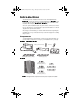
07395.062 Rev E Body D121.fm Page 1 Monday, December 1, 2003 10:52 AM ,QWURGXFWLRQ This manual provides installation instructions for the DriveRight 600 VSS, 966 (Vehicle Speed Sensor) and DriveRight 600 VF, 9) (VSS for Ford F-250 & F-350 trucks, 2000 and later) and is also used with the VSS Installation Mounting Kits ( 966 & 9)).
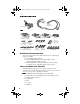
07395.062 Rev E Body D121.fm Page 2 Monday, December 1, 2003 10:52 AM +DUQHVV DQG $GDSWHU &DEOHV Digital Input Adapter Cable Harness Cable :LULQJ Red +12V Wire with Fuseholder (2) (22 AWG) Spade Terminal Sets #8-10 Studs (2) 1/4" Studs (2) (3.5 - 5 mm) (6 mm) Butt Splices (8) (26-22AWG or 24-20AWG) Blue Wire with Fuseholder (2) (22 AWG) Insulated Male Disconnects (4) (18-22AWG) T-Tap Disconnects Blue (1) Red (3) (14-16AWG) (18-22AWG) Black Ground Wire (1) (22AWG) Fuses (4) (3AG 1-1/4 x 1/4", .
07395.062 Rev E Body D121.fm Page 3 Monday, December 1, 2003 10:52 AM 3ODQQLQJ
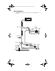
07395.062 Rev E Body D121.fm Page 4 Monday, December 1, 2003 10:52 AM :LULQJ 'LDJUDP The wiring diagram provides an overall picture of the DriveRight 600 VSS installation.
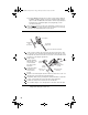
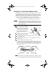
07395.062 Rev E Body D121.fm Page 5 Monday, December 1, 2003 10:52 AM ,QVWDOOLQJ 'ULYH5LJKW &DXWLRQ Always use safety stands when working under a raised vehicle. Never work under a vehicle supported only by a jack. 3URFHGXUH ,QVWDOO WKH +DUQHVV &DEOH 1RWH Make sure the harness cable and adapter cable can reach the DriveRight console mounting location before making the following connections. /RFDWH DQG 7DS 966 :LUH Locate your vehicle’s VSS wire.
07395.062 Rev E Body D121.fm Page 6 Monday, December 1, 2003 10:52 AM ❏ Or, find a known circuit that does not involve safety related equipment (headlights, tail lights, air bag, etc.) that you can tap into with an in-line splice. Possible candidate wires include those from the cigarette lighter, dome light, glove compartment light, clock, tail gate light, or other convenience functions. Tap a red wire from the fuse holder to the unswitched +12 VDC source you located in 6WHS .
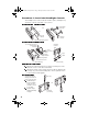
07395.062 Rev E Body D121.fm Page 7 Monday, December 1, 2003 10:52 AM 3URFHGXUH ,QVWDOO WKH $GDSWHU &DEOH Two digital inputs located on the adapter cable are available to monitor the on/off state of lights, including brake lights, or of other 12 VDC electrical accessories. Typically Digital Input 1 monitors the brake lights and Digital Input 2 monitors the headlights. In the DriveRight software Digital Input 1 is recorded in the GPS table and in the accident logs.
07395.062 Rev E Body D121.fm Page 8 Monday, December 1, 2003 10:52 AM 3URFHGXUH ,QVWDOO WKH 'ULYH5LJKW &RQVROH The DriveRight console can be mounted in a number of places, including the top of the dash, on the face of the dash, or on a sun visor.
07395.062 Rev E Body D121.fm Page 9 Monday, December 1, 2003 10:52 AM 3URFHGXUH )LQLVK WKH ,QVWDOODWLRQ Use the following steps to finish the installation. 1RWH It is not necessary to enter a code in order to perform this test. Do not enter a code until you read the user’s manual. ,QVWDOO %DWWHU\ Insert the battery into the DriveRight console as shown. &RQQHFW &RQVROH WR $GDSWHU &DEOH Connect the adapter cable to the console cable.
07395.062 Rev E Body D121.fm Page 10 Monday, December 1, 2003 10:52 AM &RQILJXUH WKH 966 6LJQDO 6HWWLQJV Because not all VSS signals are the same, you may need to change the default DIP switch setting on the VSS inline circuit. ❏ Switch 1 is used for square VSS Dip Switch wave VSS signals which do not go to ground. ❏ Switch 2 AC couples the signal in and is used for sine wave VSS signals. ❏ Switch 3 improves the sensitivity of AC coupled signals. ❏ Switch 4 turns on the LED test circuit.
07395.062 Rev E Body D121.fm Page 11 Monday, December 1, 2003 10:52 AM 966 ',3 6ZLWFK )ORZ &KDUW Use this flow chart to determine the optimum VSS dip switch setting. Set Yes 1 2 3 4 0 = OFF 0 1 0 1 1 = ON Drive 2 mph. Green LED flashing or dimmed? No Set 1 2 3 4 1 1 0 1 Drive 2 mph. Green LED flashing or dimmed? Yes No Set 1 2 3 4 1 0 1 1 Drive 2 mph. Green LED flashing or dimmed? Yes Turn Test LED Off (SW4) and you are done. No VSS not working. See Troubleshooting.
07395.062 Rev E Body D121.fm Page 12 Monday, December 1, 2003 10:52 AM 7URXEOHVKRRWLQJ If your speed is not registering correctly, consult the following check list to help you identify the cause of the problem. ❏ Make sure the display is reading in the units (km/hr or mph) you expect. Hold down the Set/Clr button in the Current Screen to change the units. ❏ Make sure the unit has been calibrated correctly. Check the calibration section of the DriveRight User’s Guide.
07395.062 Rev E Body D121.fm Page 13 Monday, December 1, 2003 10:52 AM 6SHFLILFDWLRQV Visit our website for additional product information: www.davisnet.com. 966 &RPSDWLELOLW\ The DriveRight can work with many different VSS signals provided the switch settings of the VSS in-line circuit are set correctly. However, if the signal does not meet the specifications below it may not work. Maximum VSS frequency: . . . . . . . 1 khz (144,000 PPM) at 25 mph Min peak to peak amplitude: . . . . .
07395.062 Rev E Body D121.fm Page 14 Monday, December 1, 2003 10:52 AM 7HFKQLFDO 6XSSRUW If you are experiencing problems with your DriveRight, first check the cable connections and verify the calibration settings. If you are unable to solve the problem, please call Davis Technical Support. We’ll be glad to help. Most questions can be answered on the phone. You can also email us for support, or visit our website. Sorry, we are unable to accept collect calls.