
User guide


C3 User Guide
34
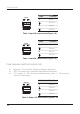
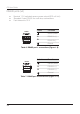
RF antenna connections (x4)
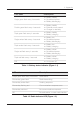
• $POOFDUJPOTBWBJMBCMFXJMMEFQFOEPODPOæHVSFESBEJPUFDIOPMPHZNJY
• All connections are standard polarity
Connector Type Function
UHF (Figure 2-5) BNC Long range UHF antenna (~450-470 MHz)
xG (Figure 2-6) SMA Cell based packet radio antenna (eg. GSM, 3G)
900 (Figure 2-7) SMA Short range spread spectrum antenna (900 MHz)
GPS (Figure 2-8) SMA Default GPS antenna
Table 10. RF connections
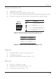
A2. User interface reference
The C3 module makes use of a number of tricolour indicators to denote various
states and modes of operation. There is also a primary user/power button, a reset
CVUUPOBOEBOBVEJPGFFECBDLNFDIBOJTNUPBTTJTUJOMPDBMDPOæHVSBUJPOBOE
control tasks.
Indicator keys
With the exception of the battery status indicator the C3 module must be in user
mode for the indicators to be actively showing state. This is a power conservation
measure. User mode can be activated by a short press of the power/user button
or alternatively if the C3 module is housed within the optional solar enclosure user
mode will become active automatically when the door is opened. With no further
activity user mode will deactivate after 30 minutes.