
User guide

C3 User Guide
48
A7. Supported sensing and control devices
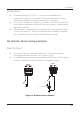
Observant V1 camera
Description
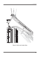
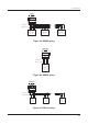
The V1 is a low-power, ruggedised, colour still image camera. It communicates to
and is powered by the C3 via a 4-way connection (Figure 22). For more information
refer to the V1 product sheet and user guide.
Electrical connection
• The V1 is a standard Modbus serial communications device and is
supplied with the Observant 4-way device connector
• The standard C3 device cable (DTC) is 6 m in length, this may be
shortened if desired by re-wiring the terminal block end
• If a longer cable run is needed the 10 m device extension cable (DCE) can
be used
• Either RS485 port on the C3 may be used
Installation notes
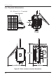
• The V1 can mount to the same pole as the C3 using the provided pole
mount bracket
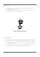
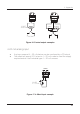
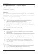
• )JHIRVBMJUZçFYJCMFDPOEVJUPSTUBOEBSESJHJEFMFDUSJDBMDPOEVJUDBOCFVTFE
to protect the cabling (Figures 23 and 24)
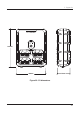
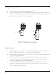
• Alternatively, if elevation allows the V1 can be mounted directly into the
32 mm bottom entry hole of the C3 (Figure 25)
• Always ensure the V1 body vent hole is oriented downward
• Ensure that the vertical adjustment bolt is fully tightened after aiming
• The 4-way device connector can be threaded through standard 25 mm
electrical conduit
Product codes
• V1: Complete V1 with 4-way device connector tail and mounting bracket
• DTC: 6 m 4-way device cable (required for connection to C3)
• DTE: 10 m 4-way device cable extension