WI REL ESS LEAF & SOIL MOISTURE/ TE M P E R A T U R E S T A T I O N INSTALLATIO N M ANUAL F O R W I R E L E S S V A N T A GE P R O ® OR VANTAGE PRO PLUS™ The Wireless Leaf & Soil Moisture/Temperature Station (referred to in this document at the Leaf/Soil Station) can be used with any Wireless Vantage Pro weather station to measure leaf wetness, soil moisture or temperature.
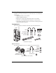
Tools for Setup In addition to the components shown, you will need some or all of the following materials: • Adjustable wrench or 7/16" wrench • Medium Phillips Screwdriver • Ballpoint pen or paper clip (small pointed object of some kind) • Drill and 3/16" (5 mm) drill bit (if mounting on a vertical surface) • Stepped Sensor Installation Tool for Soil Moisture and Temperature Sensors (recommened, see page 17) Components The Leaf/Soil Station includes the following components and hardware: Shelter U-Bolts 1
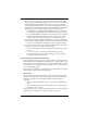
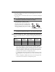
Soil Moisture Sensor with 15' (4.6 m) of cable Temperature Probe with 15' (4.6 m) of cable Optional Soil Moisture Sensor (#6440) and Optional Temperature Sensor (#6470) Installation Steps For ease of installation and use of your Leaf/Soil Station, please follow steps in the order presented.
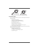
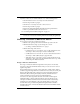
Preparing the Leaf/Soil Station The following illustrations show the location of the DavisTalk transmitter DIP switches, the battery mounting location, the modular connectors used by the leaf wetness sensors, and the terminal blocks used to connect the soil moisture sensors and temperature probes. Installing the Battery 3-Volt Lithium Battery 1. Insert the 3-volt lithium battery into the battery holder, matching the “+” sign on the battery with the “+” sign next to the battery mounting brackets.
Note: The soil moisture sensor must be moist to be used for this test. A completely dry sensor will not register on the console. Soil Temperature Sensor Connection • Temporarily connect a temperature probe to the TEMP 1 terminal block connector. • Use a pen or small screwdriver to open the connector “jaws” as shown in the illustration. • While the jaws are open, insert the temperature probe leads, then let the connector jaws close in on the lead.
. Battery Holder ON 1 2 3 4 DIP Switches DavisTalk Transmitter DIP Switches in Top-right Corner of SIM Setting Console/Receiver(s) to Same ID 1. Put your console into Setup Mode — press and hold the DONE key and press the DOWN (-) arrow key. • The console will show you the words: “RECEIVING FROM...” and “STATION NO.” followed by the transmitter IDs that your console detects. One of these should be the ID number you just set on the Leaf/ Soil Station transmitter.
Testing Station Communications 1. If you are using a Soil Moisture sensor to test the station, press the TEMP key until you see “SOIL MOIST” displayed on the console screen where the inside temperature is usually displayed. If you are using a Leaf Wetness sensor, press the HUM key until you see “LEAF WET” displayed where you usually see the inside humidity. Both the TEMP and HUM keys will display temperatures if you are using a temperature probe to test the station.
If the LED flashes repeatedly but your console isn’t picking up a signal anywhere in the room, it could be related to one of the following causes: • The DIP switches were not correctly set on the transmitter. • Review the procedure on page 5. • The ID was not correctly set on the console/receiver. • Review the procedure on page 6. • Reception is being disrupted by RF (radio frequency) interference. • There is a problem with the console/receiver. See “Contacting Davis Technical Support” on page 19.
Testing Transmission from Proposed Location It is very important to test reception from the proposed location before permanently mounting the Leaf/Soil Station. • Place the shelter at the intended mounting site, or have someone hold it there, so you can walk around with the console/receiver for a few minutes. Rotating the antenna may help to improve reception. • Test wireless reception anywhere you might want to use or mount your console/receiver now or in the future. Take your time.
3. Using an adjustable wrench or 7/16" wrench, tighten the nuts. 4. Place the second U-bolt around the pole and through the two holes at the bottom of the shelter. 5. Put a flat washer, a lock washer, and a hex nut on each bolt end, and tighten the hex nuts. Note: If no soil temperature probe is used, the console will use a default temperature of 75ºF (24ºC) to compensate the soil moisture sensor readings. 6. To prevent fraying or cutting of cables, secure them so they will not whip about in the wind.
• If you have installed any soil moisture sensors (SOIL 1, SOIL 2, SOIL 3), the corresponding temperature probes (TEMP 1 for SOIL 1, etc.) will be used to provide temperature compenstation for the soil moisture sensor readings. • If you want to use a temperature sensor for something besides compensation for a soil moisture sensor, then you cannot use the corresponding soil moisture sensor.
Finishing the Sensor Connections to the Station 1. Secure sensor cables to the cable tie mounts located next to the grommets. When tightening cable tie, make sure cables are on top of cable tie mount. Cable Tie Cable Tie Mount Securing Sensor Cables 2. To prevent fraying or cutting of cables, secure them so they will not whip about in the wind. Secure a cable to a metal pole by wrapping electrical tape around them both.
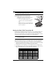
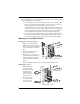
Mounting the Sensor on a Pipe To mount the sensor on a pipe, stake, or pole with outside diameter between 1" and 1-1/4" (25 mm and 31 mm), secure the sensor to the pipe using the 1-1/2" U-bolts, 1/4" flat washers, and 1/4" hex nuts as shown below. Use a 7/16" wrench or adjustable wrench to tighten the hex nuts.
4. Each matched temperature probe and soil moisture pair must use the matching connectors. If a temperature probe is not used, the soil moisture reading can be off as much as 1% for every 1°F (0.5°C) difference between the soil temperature in the soil temperature.
2. To prevent fraying or cutting of cables, secure them so they will not whip about in the wind. Secure a cable to a metal pole by wrapping electrical tape around them both. Make sure cables are secure by placing clips or ties approximately every 3 – 5' (1 – 1.6 m). Cable Tie Cable Clip Securing Cables with Clips and Ties Note: Do not use metal staples or a staple gun to secure cables. Metal staples — especially when installed with a staple gun — have a tendency to cut the cables.
Sensor Depths Sensor depth depends on the rooting depth of your crop, and also depends on soil depth and texture. Some crops need measurement at more than one depth Sensor depth dependent on: • crop rooting depth • soil texture and depth Co-locate temperature probes and moisture sensors Sensors must be located in the effective root system of the crop • With shallow rooted (less than 12”) vegetable crops, one depth may be adequate.
CAUTION: In gravelly soils and with deeper sensors, carefully install the sensor to prevent damaging the membrane. • Lack of a snug fit is the biggest problem in obtaining good soil moisture sensor readings. • The ideal way of making the access hole is to use a stepped installation tool. The stepped tool makes an oversize hole for the upper portion and an exact sized hole at the bottom where the sensor is located.
3. Press the sensors into the soil at about a 45 degree angle into the side of the trench to set the sensors about 3”-5” below the soil surface. Make sure they are good and snug in the soil. 4. Set the plug removed from the trench and compact it back into place. It will repair itself in short order. 5. Run the wires to the Leaf/Soil Station and connect them as described in “Connecting Soil Moisture and Temperature Sensors” on page 13. 6.
Troubleshooting the Sensors If you are having problems with your station, please check all sensor cable connections. Cable connections account for a large portion of potential problems. Use these tests to verify the correct operation of your soil moisture sensor: 1. With the sensor submerged in water, the station should show a reading between 0 and 5. 2. Let the sensor air dry for 30 to 48 hours. Depending on ambient temperature, humidity, and air movement, the reading should be 150 or over. 3.
Specifications Let Wetness range: 0 to 15 Soil Moisture range: 0 to 200 centibars Temperature range (Station & Temp Probe): –40 to 150° Fahrenheit (–40 to 65° Celsius) Temperature range (Soil Moisture Sensor): 32 to 105° Fahrenheit (0 to 40° Celsius) Primary power input: Solar power – Davis solar charger Secondary (backup) power: CR-123A 3-volt lithium battery Wireless transmission frequency: 916.5 MHz (868.