athena Includes: SmartCard On-Board Reader (# 8105) SmartCard Desktop Reader (# 8108) SmartCards, Pack of 10 (# 8112) Starter Interrupter Kit (# 8116) ® Davis Instruments, 3465 Diablo Avenue, Hayward, CA 94545-2778 U.S.A. • 510-732-9229 • www.davisnet.
Table Of Contents Introduction . . . . . . . . . . . . . . . . . . . . . . . . . . . . . . . . . . . . . . . . . . . . . . . . . . 1 The SmartCard System . . . . . . . . . . . . . . . . . . . . . . . . . . . . . . . . . . . . . . . . . 1 On-Board Reader Installation . . . . . . . . . . . . . . . . . . . . . . . . . . . . . . . . . . . . 3 Connecting the On-Board Reader . . . . . . . . . . . . . . . . . . . . . . . . . . . . . . . . . 4 Mounting the On-Board Reader . . . . . . . . . . . . . . . . . . . . . .
® The DriveRight SmartCard System Introduction ® The DriveRight SmartCard System allows you to download DriveRight data from any DriveRight device using the SmartCard On-Board Reader (# 8105), transport it to a computer easily using the SmartCard Desktop Reader (# 8108) and SmartCards (# 8112), and also transfer administrative data from the computer to the DriveRight.
The SmartCard System The DriveRight Fleet Management Software (FMS) is used to configure the SmartCard with pertinent information, such as the assigned vehicle, Driver ID, and card type. There are two card types that can be assigned to a SmartCard: • Driver SmartCard — Is assigned to a driver and contains a unique driver ID the DriveRight uses to verify authorized drivers. The card contains the Driver ID and receives downloaded information from the On-Board Reader by the push of a button.
On-Board Reader Installation SmartCard Desktop Reader The Desktop Reader is connected to a computer via a free USB port. The Desktop Reader works in conjunction with the FMS software to download DriveRight data via the SmartCard and to configure all the SmartCards or DriveRight devices in the fleet.
Connecting the On-Board Reader ® Velcro Tabs (6) SmartCard On-Board Reader Double-Sided Foam Tape (8) SmartCard 5-1/2" Cable Ties (8) #6 X 1/2" Flat Head Self-Tapping Screws (3) Connecting the On-Board Reader The On-Board Reader is installed in series between the DriveRight 600 or 600E device and the DriveRight digital input adapter cable or GPS module.
Mounting the On-Board Reader 3. Connect the On-Board Reader’s male connector to the female connector attached to the GPS module cable or the Digital Input Adapter Cable. See the diagrams below for help on disconnecting and connecting the cables properly: Disconnecting Cables: Hold both cables by their connector housing and pull apart. The housing of the male connector slides to separate the cables.
Mounting the On-Board Reader Thread the DriveRight connector cable down one of the large inner grooves. Thread the GPS module or Digital Input connector cable down the other large inner groove. Thread the Starter Interrupter Cable down one of the thinner outer grooves depending on your wiring orientation. Do this before mounting. Once your mounting option is in place, it may be hard to secure the wires into the grooves.
Mounting the On-Board Reader Mounting with Customer-Provided Mounting Plate If the other mounting options do not work for you, you can create your own mounting plate using the following diagram: 4" (102 mm) Width 1/4" (7 mm) Thick 1-1/2" (39 mm) Height This diagram depicts a mounting plate 4'' wide, 1-1/2'' tall, and 1/4'' thick. The mounting plate sizing can vary depending on mounting and installation needs.
Mounting the On-Board Reader 2.25" (57 mm) 11/64" (4.4 mm) Hole with countersink Template to scale To install the optional mounting plate: #6 x 1/2" Self-Tapping Screws 1. Place the mounting plate, with the preHoles for mounting plate screws drilled countersink (screws not supplied) holes facing outward, on the back of the On-Board Reader. 2. Line up the holes with countersinks with the pre-drilled holes on the On-Board Reader located on the outside of the wire grooves. 3.
Using the On-Board Reader Using the On-Board Reader Logging In To log in to the On-Board Reader, simply insert the supplied SmartCard into the OnBoard Reader before starting up the vehicle. For ease of use, you can log in with the SmartCard in one of two ways, using Swipe Mode or Leave-in Mode. To log in using Swipe Mode, simply insert the SmartCard, wait for the green indicator light and remove the SmartCard within 5 seconds.
Using the On-Board Reader logs a user out in 10 minutes, but automatic logout time can be set to any time period using the DriveRight FMS software.The Auto Logout time period is stored on each SmartCard and can be set individually for every vehicle and driver in the fleet. Auto Logout occurs if the time period elapses with no vehicle activity logged on the DriveRight device. The Auto Logout timer is reset every time a driver has logged in, new vehicle activity is recorded, or a download has occurred.
Using the Desktop Reader ight. Use the Administrative SmartCard to change settings on multiple DriveRight devices in sequence. To upload configuration information to a DriveRight: 1. With the vehicle stopped and the motor off, insert the administrative SmartCard. A blinking yellow light indicates that the upload is in progress. 2. Take the card out when the green indicator lights.
Installing the Starter Interrupter Kit Components The Starter Interrupter Kit comes with the components and hardware shown in the following illustration. Make sure you have all the necessary components before proceeding: Relay with Harness Butt Splices (16-22AWG) In-Line Splices #8 x 3/4" Sheet Metal Screw #8 Flat Washer Installation and Wiring The Starter Interrupter Kit is installed between the On-Board Reader and the vehicle’s starter switch wire.
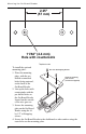
Installing the Starter Interrupter Kit . Starter 60 Amp Solenoid Starter Power Key Switch 12V Starter Switch Wire Butt Splice Butt Splice In-Line Splice Red Wire Green Wire STARTER INTERRUPTER RELAY #8116 Yellow Wire Green Wire Butt Splice Gray Wire To connect the Starter Interrupter Kit to the On-Board Reader and the Vehicle’s Ignition System: 1. Find your vehicle’s fuse box and remove the fuse for the 12-volt line before installing the Starter Interrupter Kit. 2.
Specifications Specifications On-Board Reader (# 8105) Operating Temperature. . . . . . . Storing Temperature . . . . . . . . . Primary Power . . . . . . . . . . . . . Dimensions (Unit Only) . . . . . . Dimensions (Product Package) . Weight (Unit Only) . . . . . . . . . . Weight (Product Package) . . . . . . . . . . . . -40º F to +185º F (-40º C to +85º C) . -40º F to +185º F (-40º C to +85º C) . 11 to 18 VDC (12 VDC nominal) . 2.88'' x 1.25'' x 4.13'' (73 mm x 31 mm x 105 mm) . 9.63'' x 1.75'' x 6.