IRELESS S OIL M OISTURE / T EMPERATURE S TATION W I NSTA LLA TION M AN UAL The Wireless Soil Moisture/Temperature Station, referred to in this document as the Soil Moisture Station, is for use with Wireless Vantage Pro® Weather Stations. One Soil Moisture Station can be installed per Vantage Pro Weather Station. Up to four WATERMARK soil moisture sensors and four multitemperature probes can be installed in a Soil Moisture Station.
U-Bolts 1/4" Flat Washers 1/4" x 1-1/2" Lag Screws 1/4" Lock Washers 1/4" Hex Nuts Mounting Hardware Tools for Setup In addition to the components shown, you will need some or all of the following materials: • Adjustable wrench or 7/16" wrench • Ballpoint pen or paper clip (small pointed object of some kind) • Drill and 3/16" (5 mm) drill bit (if mounting on a vertical surface) • Stepped Sensor Installation Tool (see page 13) Installation Steps For ease of installation and use of your Soil Moisture Stat
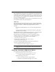
-Volt Lithium Battery DIP Switches Terminal Blocks Sensor Interface Module on Soil Moisture Station 2. Temporarily connect a temperature probe to the TEMP 1 terminal block connector. • Use a pen or small screwdriver to open the connector “jaws” as shown in the illustration. • While the jaws are open, insert the temperature probe leads, then let the connector jaws close in on the lead. 3. Temporarily connect a soil moisture probe to the SOIL 1 terminal block connector.
Setting the DavisTalk Transmitter ID Each wireless transmitting station must be set to one of eight DavisTalk transmitter IDs. DIP switches #1, 2 and 3 on the SIM allow you to control the ID — the “channel” the station will transmit on. (DIP switch #4 is used for transmission testing, not for transmitter ID.) Note: A DavisTalk transmitter and receiver communicate with each other only when both are set to the same ID. The factory default transmitter ID is ‘1’.
Setting Console/Receiver(s) to Same ID 1. Put your console into Setup Mode — press and hold the DONE key and press the DOWN (-) arrow key. The console will show you Screen 1: Transmitters. You should see the words: “RECEIVING FROM...” and “STATION NO.” followed by the transmitter IDs that your console detects. One of these should be the ID number you just set on the Soil Moisture Station transmitter.
Troubleshooting Communication Problems First, verify that the console/receiver is powered and is not in Setup Mode (exit Setup Mode by pressing DONE key and holding it for a moment). Then, on the Soil Moisture Station, check that the battery is properly installed. Walk around the room with the console, standing for a few moments in various locations to see if you are picking up signals.
Range of Wireless Transmission The range of wireless transmission depends on many factors. For the best reception, position the transmitter shelter and your console/receiver as close together as possible. The maximum range is up to 400' (120 m) in the line of sight, under optimal conditions. Typical range under most conditions is 100' to 200' (30 to 60 m), but this may be reduced by walls, ceilings, trees, or foliage. Radio-frequency interference (RF) can also reduce transmission distance.
Mounting the Soil Moisture Station Mounting on a Pole 1. While holding the shelter against the pole, place a U-bolt around the pole and through the two holes on at the top of the shelter. 2. Place a flat washer, a lock washer and a hex nut on each of the bolt ends. Flat Washer Hex Lock Nut Washer U-Bolt Mounting Soil Moisture Station on a Pole 3. Using an adjustable wrench or 7/16" wrench, tighten the nuts. 4.
Connecting the Sensors 1. Run the sensor cables up through the grommets on the bottom of the station housing. 2. Connect the temperature probes to the TEMP connectors. 3. Connect soil moisture probes to the SOIL connectors 4. Each matched temperature probe and soil moisture pair must use the matching connectors. If a temperature probe is not used, the soil moisture reading can be off as much as 1% for every 1°F (0.5°C) error in the soil temperature.
6. To prevent fraying or cutting of cables, secure them so they will not whip about in the wind. Secure a cable to a metal pole by wrapping electrical tape around them both. Make sure cables are secure by placing clips or ties approximately every 3 – 5' (1 – 1.6 m). Cable Tie Cable Clip Securing Cables with Clips and Ties Note: Do not use metal staples or a staple gun to secure cables. Metal staples — especially when installed with a staple gun — have a tendency to cut the cables.
Sprinkler Irrigation • Sprinkler irrigation usually provides a more uniform distribution of water to the ground surface, but there can be great differences in penetration and holding capacity due to soil type variations, soil interfaces and contour. Try to place your sensors in the areas where variations occur. • In tree crops, locate sensors at the drip line. • In row crops, locate sensors right in the plant row.
• With coarse, shallow or layered soils, root systems may be limited in depth. • Guidelines on proper depths for specific crops and conditions can be obtained from your local farm advisor. Some crops need measurement at more than one depth Sensor depth dependent on: • crop rooting depth • soil texture and depth Co-locate temperature probes and moisture sensors Sensors must be located in the effective root system of the crop Installation Procedure 1. Soak the soil moisture sensors overnight in water.
• Lack of a snug fit is the biggest problem in obtaining good soil moisture sensor readings. • The ideal method of making the access hole is to have a stepped tool. This makes an oversize hole for the upper portion and an exact sized hole at the bottom where the sensor is located. 4. After installing the soil moisture sensor, the hole needs to be carefully backfilled and tamped down to prevent air pockets which could allow water to channel down to the sensor.
Installation Procedure for Turf/Lawns 1. Cut a slight “V” shaped trench about 5” wide at the top and about 6” deep into the turf--about 6” long. 2. Lift out the turf plug piece you just cut. 3. Press the sensors into the soil at about a 45 degree angle into the side of the trench to set the sensors about 3”-5” below the soil surface. Make sure they are good and snug in the soil. 4. Set the plug removed from the trench and compact it back into place. It will repair itself in short order. 5.
Using Soil Moisture Readings Use this table as a general guide to interpret soil moisture readings. Monitoring the soil moisture readings, and comparing them to your field or lawn conditions over time, will help you develop a better understanding of how to interpret your soil moisture readings. Centibar Reading Soil Condition 0-10 Saturated Soil. Occurs for a day or two after irrigation.
Specifications • Soil Moisture range: 0 to 200 centibars • Temperature range (Station & Temp Probe): –40 to 140° Fahrenheit (–40 to 60° Celsius) • Temperature range (Soil Moisture Sensor): 32 to 105° Fahrenheit (0 to 40° Celsius) • Primary power input: Solar power – Davis solar charger • Secondary (backup) power: CR-123A 3-volt lithium battery • Wireless transmission frequency: 916.5 MHz • 868.