Integrated Sensor Suite Installation Manual for Vantage Pro Weather Stations Product # 6320, 6320C, 6321, 6321C, 6325, 6325C, 6326, 6326C
Contents Introduction . . . . . . . . . . . . . . . . . . . . . . . . . . . . . . . . . . . . . . . . . . . . . . . . . . . . . . . . 1 Preparing the ISS for Installation . . . . . . . . . . . . . . . . . . . . . . . . . . . . . . . . . . . . . . . 2 Siting the ISS and Anemometer . . . . . . . . . . . . . . . . . . . . . . . . . . . . . . . . . . . . . . . . 9 Installing the ISS . . . . . . . . . . . . . . . . . . . . . . . . . . . . . . . . . . . . . . . . . . . . . . . . . . .
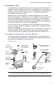
Introduction: Included Components and Hardware Introduction The Integrated Sensor Suite (ISS) collects outside weather data and sends the data to a Vantage Pro console or Weather Envoy. Wireless and cabled versions of the ISS are available, as well as standard and plus versions. The Wireless ISS is solar powered and sends data to the console via a low-power radio. The Cabled ISS sends data and receives power via the console cable.
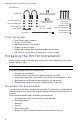
Preparing the ISS for Installation: Tools for Setup Hardware #6 x 1/2" (3.5 x 12 mm) Self-Threading Screws (2) U-Bolts (2) 1/4" Flat Washers (4) 1/4" x 3" (~6 x 75 mm) Lag Screws 3-Volt Lithium Battery (Wireless ISS only) 1/4" Lock Washers (4) 1/4" Hex Nuts (4) Backing Plate .
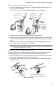
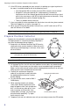
Preparing the ISS for Installation: Assemble the Anemometer Attaching Anemometer Arm to Base 1. Insert the anemometer arm into the base, sliding the cable through the notch in the base as shown in illustration. Be sure to line up the small hole in the arm with the holes in the base. Insert anemometer arm into base #4-40 Hex Nut #4 Tooth Lock Washer Slide cable through notch #4 Flat Washer #4 x 1-1/8" Machine Screw Important: Press cable firmly into channel 2.
Preparing the ISS for Installation: Check SIM Sensor Connections 3. Push the wind cups up onto the anemometer’s stainless steel shaft. Push cups onto stainless steel 4. Slide the wind cups up the shaft shaft as far as possible. Tighten set 5. Use the Allen wrench provided screw with to tighten the set screw on the Allen wrench side of the wind cups. When Attaching Wind Cups you let go of the wind cups, they should drop slightly. 6. Spin the wind cups. 7.
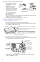
Preparing the ISS for Installation: Cabled ISS: Powering and Testing Connect the Anemometer Cable to the SIM 1. Unwind the coil of cable enough to work with the anemometer. Do not unwind the entire coil of anemometer cable just yet. 2. Gently insert the end of the anemometer cable into the connector labeled “WIND” on the SIM. 3. Press the cable fully into the channel next to the connector as shown on the next page.
Preparing the ISS for Installation: Wireless ISS: Powering and Testing Troubleshooting Cabled ISS Communication If your console is not receiving sensor readings from the ISS, please try the following troubleshooting procedures. 1. Check the console to make sure you are using the supplied AC adapter. Other adapters may not work. 2. Make sure the console cable is firmly plugged into the ISS connector on the console. 3.
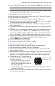
Preparing the ISS for Installation: Wireless ISS: Powering and Testing 4. If you see the ISS ID number, press and hold down the DONE key to view ISS data. Note: Be sure to allow up to a minute for the ID number to appear on the screen. 5. If the console does not display the number of the ISS transmitter ID setting, refer to “Troubleshooting Wireless ISS Reception” later in this section. Verifying Data from the ISS Sensors Your console should now display weather readings from the ISS.
Preparing the ISS for Installation: Prepare the Rain Collector 6. If the LED flashes repeatedly but your console isn’t picking up a signal anywhere in the room, it could be related to one of the following causes: • You changed the ISS transmitter ID at the ISS or console, but not at both. • Reception is being disrupted by RF (radio frequency) interference.
Siting the ISS and Anemometer: General ISS Siting Guidelines: Siting the ISS and Anemometer For your weather station to perform at its best, use these guidelines to select the best mounting locations for your ISS and anemometer. Be sure to take ease of access for maintenance, sensor cable lengths and wireless transmission range into consideration when siting your station. General ISS Siting Guidelines: • Place the ISS at least 5' (1.5 m) away from sources of heat such as chimneys and exhaust vents.
Siting the ISS and Anemometer: General ISS Siting Guidelines: • Range may be reduced by walls, ceilings, trees, foliage, a metal roof or other large metal structure or objects such as aluminum siding, metal ducting, and metal appliances such as a refrigerator. • Radio-frequency interference (RFI) will also reduce transmission distance. Cordless phones (900 Mhz) and ham radios are common examples of RFI.
Installing the ISS: General ISS Installation Guidelines Installing the ISS The anemometer and the main part of the ISS can be installed either together as a single unit on a pole, or apart from each other. The main part of the ISS includes the rain collector, the temperature and humidity sensors, the radiation shield, and the SIM housing. Use the U-bolts to install the ISS and anemometer the together or separately on a pole. Use the lag screws to install them separately on a flat, vertical surface.
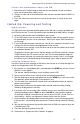
Installing the ISS: Installing the ISS on a Flat Surface Installing the ISS on a Flat Surface Refer to the following illustration to install the ISS on a post or flat, vertical surface. Anemometer Base 1/4" Flat Washers 1/4" Lock Washers 1/4" x 3" Lag Screws Backing Plate 1/4" x 3" Lag Screws 40' of Anemometer Cable Note: Typically the anemometer and rain collector are mounted on opposite sides of the post. They are shown mounted on adjoining sides to clarify the installation details.
Installing the ISS: Installing the ISS on a Pole Installing the ISS on a Pole When installing the ISS on a pole, the rain collector and radiation shield section of the ISS can be mounted as a single unit with the anemometer section, or the two sections can be mounted separately.
Installing the ISS: Installing the ISS on a Pole Installing ISS and Anemometer Together Please remember to install your ISS so the anemometer arm is aiming North. If the arm doesn’t point North you will need to re-orient the wind vane. See “Appendix C: Re-orienting the Wind Vane” on page 21. 1. Place the U-bolt for the anemometer around the pole so that its round end will fit in the top groove of the rain collector side’s plastic mounting base. The groove is right above two large holes. 2.
Additional Mounting Options: Finishing the Installation 3. Swivel the anemometer until the arm is pointing north. If the anemometer arm is not pointing north, go to “Appendix C: Re-orienting the Wind Vane” on page 21 after tightening the nuts. 4. Using an adjustable wrench or 7/16" wrench, tighten the nuts. Finishing the Installation Level the Solar and UV Sensors If your station includes a solar or UV sensor, use the bubble level on the sensor as a guide to verify that the sensor is level.
Maintenance: Relocating the Anemometer Relocating the Anemometer Using Extension Cables: Note: Not all cables are compatible with your Vantage Pro system. To be sure they will work, order Davis extension cables from your dealer or directly from Davis Instruments. If you would like to locate the anemometer more than 40’ (12 m) from the ISS, use our extension cables #7876. Be aware that the maximum measurable wind speed reading decreases as the total length of cable from the anemometer to the ISS increases.
Troubleshooting: Cleaning the Radiation Shield Cleaning the Radiation Shield Check the radiation shield for debris or insect nests at least once a year and clean when necessary. A buildup of material inside the shield will reduce its effectiveness and may cause inaccurate temperature and humidity readings. 4" Bolt Lock Washer Flat Washer To clean the radiation shield: 1. Remove the rain collector cone. 2.
Troubleshooting: The Most Common Anemometer Problems The Most Common Anemometer Problems Note: If the anemometer is sending no data, the wind display indicates 0 speed and a North direction. “The anemometer head is tilted when I mount the anemometer.” With your Allen wrench, loosen the screws holding the anemometer head on the arm. (The screws are on the bottom of the anemometer head, by the wind cups.) Turn the anemometer head so it is straight and then tighten the screws.
Appendix A: Wireless Transmitter IDs: Changing ISS Transmitter ID Appendix A: Wireless Transmitter IDs Changing ISS Transmitter ID Each wireless transmitting station, including the Integrated Sensor Suite (ISS), uses one of eight selectable transmitter IDs. DIP switches #1, 2 and 3 on the transmitter allows you to control the ID — or “channel” — the station will transmit on. (DIP switch #4 is used for transmission testing, not for transmitter ID.
Appendix B: Optional Accessories: Using Multiple Transmitting Stations Using Multiple Transmitting Stations This table shows the maximum number of each type of station that can be used with a single Vantage Pro console.
Appendix C: Re-orienting the Wind Vane: Other Accessories Appendix C: Re-orienting the Wind Vane Your Vantage Pro station is configured to register wind direction correctly if the anemometer points to true North. If you are unable to mount the anemometer shaft pointing to true North, use the following instructions to correct the wind vane orientation. • Do not rely on a compass unless it is properly calibrated. In North America there can be up to 15° variation between true North and a raw compass reading.
Specifications Complete specifications for the ISS and other products are available in the Weather Support section of our website: www.davisnet.com. Cabled ISS Temperature range: . . . . . . . . . . . -40 to 140° Fahrenheit (-40 to 60° Celsius) Power input: . . . . . . . . . . . . . . . . Console Cable from Vantage Pro console Wireless ISS Temperature range: . . . . . . . . . . . -40 to 140° Fahrenheit (-40 to 60° Celsius) Transmission frequency: . . . . . . . 916.5 MHz for North America 868.