III & IV Series Mobility Scooter Owner’s Manual Daymak Inc. · 130 Oakdale Rd · Toronto, ON · M3N 1V9 416.749.2324 · 1.866.379.7779 · www.daymak.
Introduction Thank you for purchasing Daymak’s Boomerbuggy Mobility Scooter. We thank you for choosing a Daymak scooter, especially one that has been designed to provide you with years of trouble free, comfortable, quiet, and eco-friendly service. Your scooter has been equipped with the latest technologies that assist in providing you with the most efficient and comfortable ride you’ve ever felt. We at Daymak Inc.
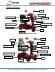
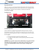
Diagrams and Specs Mirrors Control Panel Adjustable Armrests Carrier Basket Cup Holder Seat Reflectors Tiller / Steering Colum Rear Lights / Indicators Headlights Anti-Tip Wheels Tires Foot Rest Boomerbuggy III Reference Guide Mirrors Headrest Control Panel Seat Adjustable Armrests Cup Holder Carrier Basket Tiller / Steering Colum Rear Lights / Indicators Headlights / Indicators Anti-Tip Wheels Tires Foot Rest Boomerbuggy IV Reference Guide Daymak Inc.
Model Overall Dimensions Gross Weight Net Weight (including batteries) Front Wheel Rear Wheel Weight Capacity Forward Speed (adjustable) Reverse Speed (adjustable) Range Turning Radius Battery Brakes Anti-Tip Wheels Bumper Motor Charger Boomerbuggy III 51.38” x 25.20” x 46.06” 96 kg / 211.64 lbs 86 kg / 189.59 lbs 10” 10” 150 kg / 330.69 lbs 6 - 8 km/h 2.4 – 4.8 km/h Up to 45 km per charge 47.
Model Overall Dimensions Gross Weight Net Weight (including batteries) Front Wheel Rear Wheel Weight Capacity Forward Speed (adjustable) Reverse Speed (adjustable) Range Turning Radius Battery Brakes Anti-Tip Wheels Bumper Motor Charger Boomerbuggy IV 55.51” 24.61” x 48.03” 105 kg / 231.48 lbs 96 kg / 211.64 lbs 10” 10” 150 kg / 330.69 lbs 6 - 9 km/h 2.4 – 4.8 km/h Up to 36 km per charge 51.
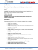
EMI Safety Information EMI Warning The increasing rate at which communication technology develops has flooded our environment with electromagnetic (EM) waves that are emitted by various sources (such as television transmitters, cellular phones, wireless technologies, and etc). Electromagnetic Interference (EMI) occurs more intensely as you approach the source of the transmission and are capable of causing your scooter to malfunction or function uncontrollably.
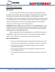
Getting to Know your Scooter Scooter Control Panel Mirrors Forward/Reverse Indicator Charge Indicator Brake Release Ignition Charging Port Fuse Forward Lever Reverse Lever Speed Adjustment Knob Turning Signals Emergency Brakes Headlight Switch Horn Ignition Place your keys in the ignition and turn clockwise one click to engage the motor. You will know the scooter is on once the LEDs light up on your control panel. To turn off your scooter, simply turn your key counter-clockwise.
Speed Controls You can adjust the speed of your scooter by turning the speed adjustment knob. The lowest setting is set by turning the knob fully counter-clockwise and the highest setting is set by turning the knob fully clockwise. Charge Indicator The number of LED bars lit indicates the amount of charge left. The true charge level will show only when the bike is in operation.
Brake Release Button While the scooter is on, pressing the brake release button will release the brakes, allowing you to physically push the scooter forward and reverse regardless of the free wheel lever’s position. Once the button is released, the brakes will automatically reengage. Free Wheel Lever Anti-Tip Wheels Free Wheel Lever Free Wheel Operation The free wheel lever engages the parking brake while the scooter is inactive.
Anti-Tip Wheels The anti-tip wheels are a safety measure that helps to prevent the scooter from being tipped over. The anti-tip wheels are located at the rear of the scooter’s frame. WARNING! The scooter should never be used unless the anti-tip wheels are in place. Failure to do so can result in injury or damage.
• DO NOT drive on an incline with oil, water, or ice on it • DO NOT try to lift the scooter by the seat, tiller, rear chassis cover, or any removable parts • DO NOT use parts of accessories that are not authorized by Daymak Inc. • DO NOT connect any medical devises to the scooter battery On the Road Please adhere to the following recommendations to ensure your safety.
SAFETY WARNING! When getting on or off the scooter, please make sure that the key is in the off position to prevent engaging the scooter accidentally. When seated comfortably, set the speed control knob according to your driving ability. We recommend that you keep the speed at the lowest setting (fully counterclockwise) until you are comfortable with higher speeds. Getting Started Before the first use, you must charge your scooter completely. This should take approximately 8 to 12 hours.
Start by gently squeezing the right lever. Gradually apply more pressure to the lever and the scooter will begin to pick up speed. If you have set your speed to the lowest, your top speed will be restricted. Once you are in motion, gently release the lever and the scooter will smoothly come to a stop. Repeat moving forward and braking a few times to get used to the motion. Next is to practice reversing. To reverse, gradually squeeze the left lever.
WARNING! Never turn sharply while the scooter is at top speed! Always exercise caution when taking corners. Failure to do so can cause injury and damage. Extra Guidelines Ramps / Slopes The stability of your scooter is governed by several factors such as seating position, the angle of the slope, your height and your weight. Take caution when approaching an incline and always head directly (perpendicular) to the slope and not at an angle. While on the slope, avoid making any turns.
Adjustment Tiller Angle Adjustment The Tiller Adjustment lever is located on the side near the bottom of the tiller. To adjust the tiller angle, hold onto the handlebar with one hand to support its weight, pull the tiller adjustment lever outwards and adjust the angle of the tiller to the desired position. When you are comfortable, tighten the lever once more. Tiller Adjustment Lever Tiller Adjustment Lever IMPORTANT! Do not drive the scooter if the tiller is not secured.
Armrest Adjustment, Swivel Adjustment and Seat Removal Armrest Adjuster Seat Removal Nut Swivel Adjustment Swivel Adjustment An alternative solution to mounting the scooter is to turn the seat outwards to sit comfortably and then turn the seat back to original position. To do this, simple pull the swivel adjustment lever outwards and the seat will loosen. Adjust the seat appropriately and return the lever to its original position. Armrest Adjustment The armrests can easily be adjusted to be wider.
Seat Removal Nut The seat removal nut is located on the shaft holding the seat, next to the swivel adjustment lever. This is a grub screw that engages a groove on the shaft that the seat is mounted on. By loosening or removing this nut, you will be able to remove the seat. Upon reinstallation, pay extra attention to ensure that the nut is secured and in place. Seat Removal After you have removed the seat removal nut, the seat can be easily removed by lifting the chair off of the shaft it rests on.
Batteries and Charger The Boomerbuggy series utilizes two maintenance free, seal lead acid batteries. Battery performance is affected by various factors including: temperature, terrain, the weight of the user, and overall usage for the batteries. The battery level indicator/gauge is only a guide for judging the amount of charge in the batteries. The true charge of the batteries will display once the scooter is in drive.
Maintenance and Troubleshooting Lubrication In six-month intervals, you should lubricate the following parts with multipurpose grease or similar lubricant: seat pivot post and seat release lever. CAUTION! Do not lubricate the transaxle gears! Wheels and Tires The wheels have split rims, which allows easy puncture repair. To change the wheel, remove the center 13mm bolt and slide the wheel off its axle. When refitting the wheel, be sure to use a locking washer and use locktite or a similar adhesive.
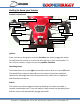
VCC GND LED9 Indicator Light ºì »Æ ºì LED10 LED12 LED13 LED10 »Æ DS1 DS2 5.1K R21 D3 1N4148 1 R19 5.1K R17 5.1K R15 5.1K DS4 LAMPS DS3 R16 5.1K R18 5.1K R20 5.1K R22 Q1 DS5 B2 B1 F2 F1 J3 S8050 K1 DS7 D5 KEYS S2 S3 J8 VCC VCC R5 5.1K VCC J4 VCC 1N4007 SRD-24VDC-SL-C DS6 1N4007 D4 1 2 3 4 5 5.
Daymak Inc. · 130 Oakdale Rd · Toronto, ON · 416-749-2324 · 1-866-379-7779 · www.daymak.
Warranty One Year Limited Warranty If assembled by a Daymak dealer, we will repair or replace parts within 90 days for parts and labour and 1 year for the motor and frame upon examination of the defect by an authorized representative. All parts that are defective in material or workmanship are covered by a manufacturer’s warranty. The warranty does not cover the shipping costs of replacement parts. Do not return faulty parts without prior consent.