
Instruction Manual

M2 User Manual
7
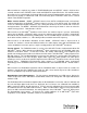
MODE - SERVICE – Default is Auto mode. Momentary push activates multicast tuning when a
multicast signal is present. Holding switch in for 5 seconds when locked to an HD Radio
TM
station,
forces monitor into Analog mode. Blue arrow LED illuminates only when switch is being pushed, or
when multicast tuning or Analog mode is active. In any active mode, second push of MODE –
SERVICE returns monitor to Auto mode.
FORCING – Activates A-D SPLIT mode for monitoring and display of HD Radio
TM
analog-to-digital level
and time alignment as well as audio phase. The analog left channel is on the M2 left channel while the
digital left channel is on the M2 right channel. Blue arrow LED illuminates when mode is active.
DATA - DISPLAY and DATA - DISPLAY Menu – Selects decoded RBDS from analog broadcast
(M2.2R only) and PAD data from an HD Radio
TM
broadcast for display on the second line of the VFD.
Momentary push DATA - DISPLAY switch scrolls display through each RBDS and HD Radio
TM
PAD
data field, as described below. Holding DATA - DISPLAY switch in for 5 seconds activates DATA -
DISPLAY menu. The firmware version, e.g., “v2.0.9 A3.2.1” is displayed for 5 seconds before
displaying the first menu option. The menu’s first selection enables or disables “Scrolling Data” mode
when tuner displays each RBDS and HD Radio
TM
PAD data field for approximately 5 seconds before
scrolling to the next field. UP or DN switches toggle the setting; pressing “SELECT” saves the setting
and increments the menu to the next field. The second menu field enables or disables “Audio Muting.”
Next press of “SELECT” saves the setting and exits the menu. Blue LED illuminates only when mode
is active. Default is AUTO mode with station short name to be displayed in second line of VFD when
tuned to an HD Radio
TM
station.
HD LOCKED – Blue LED indicator illuminates when monitor has acquired OFDM portion of an HD
Radio
TM
signal and digital carrier SN > 58dB/Hz, thereby permitting HD Radio
TM
digital audio to be
valid. HD is displayed in upper right hand corner of VFD when monitor has acquired OFDM portion of
an HD Radio
TM
signal.
MULTICAST – Blue LED indicator illuminates when monitor has acquired OFDM of an HD Radio
TM
signal and there is at least one multicast SPS signal present.
DELAY SET – Blue LED indicator illuminates when monitor has acquired OFDM of an HD Radio
TM
MPS signal and the analog diversity delay is active. The LED is off when there is no delay bit set; i.e.
“ball game mode” meaning that the analog program has not been delayed to be coincident with the HD
Radio
TM
MPS signal.
DEMODULATION LEVEL METERS – 58-segment multi-colored LED meters display demodulated
analog or digital audio levels, as described below. For analog audio programs, either de-emphasized
or pre-emphasized audio can be displayed; select pre-emphasized audio by shorting internal Pre-
Emphasis Jumper JP15 (left channel) and JP16 (right channel). Your M2 was shipped with JP15
and JP16 open to display de-emphasized audio. A Torx
TM
T-8 L-key (included) or driver is
required to remove the M2’s cover.
CARRIER MODULATION METER – 58-segment multi-colored LED meter displays the analog AM or
FM carrier level, as described below. Meter is normally off when an HD Radio
TM
broadcast is locked,
unless Analog Carrier mode is selected in the Data – Display menu. The meter has a quasi-peak
response with a floating peak-hold and displays positive or negative peaks or both simultaneously from
46% to 125% with user programmable measurement integration times of 100, 200, 500 and 1000uSec.
The measurement integration times can be changed using internal Time Integration Jumper JP1.
Your M2 was shipped from the factory preset for 100uSec integration time.