
Instruction Manual

8
M2 User Manual
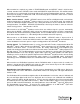
DEMODULATION LEVEL SELECT – Permits user to select Left or L+R demodulated audio level to be
displayed on top Demodulation Level meter, and Right or L–R demodulated audio level to be displayed
on bottom Demodulation Level meter. Blue LEDs indicate the user selection of display mode.
CARRIER MODULATION SELECT – Permits user to select positive, negative or both deviations to be
displayed on the carrier modulation meter. Blue LEDs indicate the user selection of display mode.
RF SIGNAL LEVEL – 8-segment green LED display indicates relative RF signal level received at the
antenna connector on the M2 rear panel. A minimum of 3 RF signal strength segments must be
illuminated (indicating >65dBf) for accurate demodulation and carrier level measurements.
M2 Operating Description
Power-up and Standby. The Power switch is located on the rear panel of the M2; when switched on
the hardware and software version of your M2 to be displayed for 3 seconds on the M2’s VFD.
In any mode, if the SELECT and DN switches are depressed simultaneously for 5 seconds, monitor
goes into Standby mode with all front panel controls and indicators blanked except for SELECT and UP
switches; the M2’s VFD then indicates the “DaySequerra Standby” message. Holding SELECT
together with UP switch in for 5 seconds when in this Standby mode reactivates all front panel controls
and indicators and returns monitor to normal operation.
Front Panel Locked. In any mode, if SELECT and MODE – SERVICE switches are depressed
simultaneously for 5 seconds, monitor goes into Front Panel Locked mode; i.e., all front panel controls
are inhibited except for UP and SELECT switches; analog and digital audio outputs continue. VFD
alternates between displaying FRONT PANEL LOCKED and normal display for tuned station.
Momentary simultaneous push of SELECT and UP switches in Front Panel Locked mode unblanks all
front panel controls and indicators, and returns monitor to normal operation. VFD displays “Exiting
Front Panel Locked Mode” message during monitor state transition.
Audio Muting. The M2’s audio output can be set to automatically mute for received signals with signal
strength less than 45dBf. The audio muting can be enabled using the DATA - DISPLAY menu
described previously.
Tuner Band Control. TUNER BAND control toggles between manual AM and FM tuning. TUNER
BAND arrow LED illuminates only when mode is active.
Presets Control. In PRESETS tuning mode monitor has capability to store 20 AM stations and 20 FM
stations including FM-HD multicast signals.
Preset stations are stored for recall in positions A1 through A20 and F1 through F20 respectively for
AM and FM bands. PRESETS Arrow LED illuminates when monitor is in PRESETS tuning mode. UP
and DN scroll through the preset stations stored for the band selected. Second momentary push of
PRESETS switch changes tuner band.