Loudspeaker Kit Assembly Instructions Dayton RS621 Speaker Kit Manual © 2008 Dayton Audio®
Introduction Your Dayton RS621 speaker kit has been designed to provide you with the basics of speaker design and construction. After completing the assembly, your RS621 speakers will provide you with a pair of speakers that are compact in size yet are BIG on sound. The RS621 kit uses two of the most popular Dayton Reference Series products; the RS28AS-4 1-1/8" Shielded Aluminum Dome Tweeter and the 8 Ohm Dayton RS150S-8 6" Reference Series Shielded Woofer.
Loudspeaker Kit Assembly Instructions By following these instructions and assembling the speaker in a conscientious manner, you will be able to enjoy your speaker for many years to come. If there are any questions during the assembly process, please contact your place of purchase. Gather the Necessary Tools The assembly of your speaker kit requires several basic tools and supplies, though more advanced tools can be used if desired.
Now that the posts are fully secured, reinstall the colored knobs on the outside of the cabinet. When looking from the rear of the cabinet (terminals should be closer to the “bottom” of the cabinet), the “red” terminal is normally positioned on the right side. 2. Install damping material The damping material included is intended to line the walls of the cabinet to reduce reflections and help prevent standing waves.
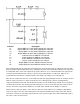
Indicator C1 C2 C3 C4 L1 L2 L3 L4 R1 R2 Description Dayton DMPC-6.2 6.2uF 250V Polypropylene Capacitor Dayton DMPC-8.2 8.2uF 250V Polypropylene Capacitor Dayton DMPC-18 18uF 250V Polypropylene Capacitor Dayton DMPC-25 25uF 250V Polypropylene Capacitor Jantzen 0.27mH 18 AWG Air Core Inductor Jantzen 0.80mH 18 AWG Air Core Inductor Jantzen 0.025mH 18 AWG Air Core Inductor Jantzen 1.5mH 18 AWG Air Core Inductor Dayton DNR-4.0 4 Ohm 10W Non-Inductive Resistor Dayton DNR-8.
We can now solder the connecting wires (red/black zipcord) for the inputs and speaker terminals. Solder the input wire from the binding posts to the woofer input, and solder a "jumper" wire from the woofer input to the tweeter input. Then solder wire to the output crossover board terminals for woofers, and tweeter (W "+ ", W "-", T "+", and T "-"). Make sure that the positive terminals are connected to the positive (red) wires in all locations and allow ample length of wire for connections.
The baffle can now be installed into the cabinet, working carefully to make sure no wires are trapped between the baffle and the cabinet. Once the baffle is fully installed, it can be secured via the included machine screws and glued into place if desired. Using the 4 machine screws by themselves will have adequate holding power to prevent leaks and vibrations of the baffle. However, for the utmost cabinet strength, the baffle should be glued into place with polyurethane glue.
Problem: There is sound from the speaker, but it doesn’t sound normal. Cause: Crossover board is wired incorrectly. Solution: Double check that the input from the speaker terminals is connecting to the inputs on the crossover board. If this is correct, check that all components are of the correct value and in the right location. Problem: Intermittent output of entire speaker, woofer, or tweeter. Cause: Bad connection in wires or crossover board.